 Yamaha XMAX YP125R - Service manual > Crankshaft (YP125R)
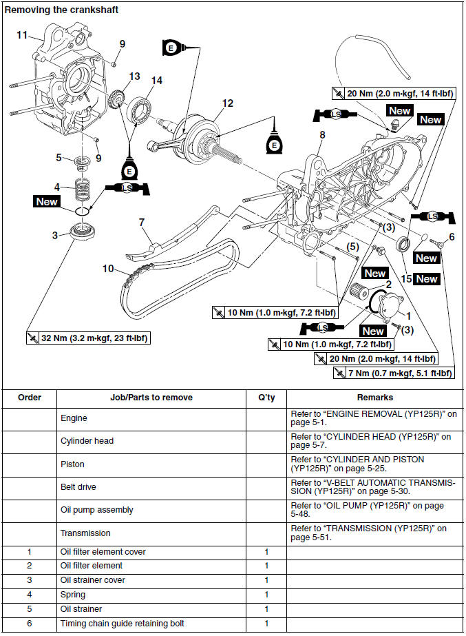
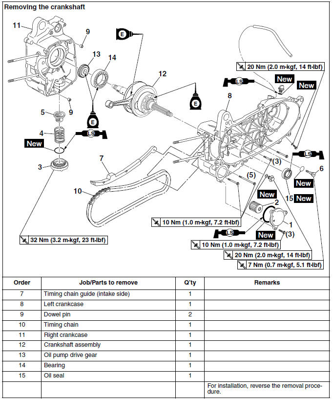
Removing the crankshaft
Removing the crankshaft
Removing the crankshaft
Disassembling the crankcase
1. Remove:
- Crankcase bolts
TIP
Loosen each bolt 1/4 of a turn at a time, in stages and in a crisscross pattern. After all of the bolts are fully loosened, remove them.
2. Remove:
- Left crankcase "1"
NOTICE
Tap on one side of the crankcase with a softface hammer. Tap only on the reinforced portions of the crankcase, not on the crankcase mating surfaces. Work slowly and carefully, and make sure the crankcase halves separate evenly.
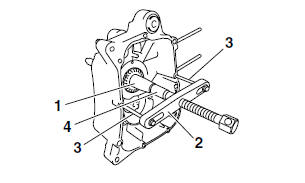
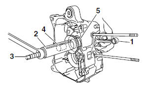
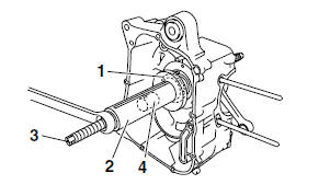
Removing the crankshaft assembly
1. Remove:
- Crankshaft assembly "1"
TIP
- Remove the crankshaft assembly with the crankcase separating tool "2" and M6 bolts "3".
- Make sure that the crankcase separating tool is centered over the crankshaft assembly.
NOTICE
- To protect the end of the crankshaft, place an appropriate sized socket "4" between the crankcase separating tool bolt and the crankshaft.
- Do not tap on the crankshaft.
 Crankcase separating tool
90890-01135
Crankcase separating tool
90890-01135
Crankcase separator YU-01135-B
Checking the timing chain and timing chain guide
1. Check:
- Timing chain
Damage/stiffness → Replace the timing chain and camshaft sprocket as a set.
2. Check:
- Timing chain guide (intake side) Damage/wear → Replace.
Checking the crankshaft and connecting rod
1. Measure:
- Crankshaft runout
Out of specification → Replace the crankshaft.
TIP
Turn the crankshaft slowly.
 Runout limit C
0.030 mm (0.0012 in)
Runout limit C
0.030 mm (0.0012 in)
2. Measure:
- Big end side clearance
Out of specification → Replace the crankshaft.
 Big end side clearance D
0.150-0.450 mm (0.0059-0.0177
in)
Big end side clearance D
0.150-0.450 mm (0.0059-0.0177
in)
3. Measure:
- Crankshaft width
Out of specification → Replace the crankshaft.
 Width A
45.95-46.00 mm (1.809-1.811 in)
Width A
45.95-46.00 mm (1.809-1.811 in)
4. Check:
- Crankshaft sprocket "1"
Damage/wear → Replace the crankshaft.
- Bearing "2"
Cracks/damage/wear → Replace the crankshaft.
5. Check:
- Crankshaft journal
Scratches/wear → Replace the crankshaft.
- Crankshaft journal oil passage
Obstruction → Blow out with compressed air.
Checking the crankcase
1. Thoroughly wash the crankcase halves in a mild solvent.
2. Thoroughly clean all the gasket surfaces and crankcase mating surfaces.
3. Check:
- Crankcase
Cracks/damage → Replace.
- Oil delivery passages
Obstruction → Blow out with compressed air.
Checking the bearing and oil seal
1. Check:
- Bearing
Clean and lubricate the bearings, and then rotate the inner race with your finger.
Rough movement → Replace.
Checking the oil pump drive gear
1. Check:
- Oil pump drive gear
Damage/wear → Replace.
Checking the oil strainers
1. Check:
- Oil strainers
Damage → Replace.
Contaminants → Clean with solvent.
Installing the crankshaft
1. Lubricate:
- Oil seals
- Bearings
- Oil pump drive gear
 Recommended lubricant
Oil seal
Lithium-soap-based grease
Bearing, oil pump drive gear
Engine oil
2. Install:
- Oil seal "1"
(to the left crankcase)
 Oil seal installed depth
0-0.5 mm (0-0.020 in)
Oil seal installed depth
0-0.5 mm (0-0.020 in)
a. Oil seal installed depth
3. Install:
- Bearing (to the right crankcase)
4. Install:
- Crankshaft assembly "1"
TIP
- Install the crankshaft assembly with the crankshaft installer pot "2", crankshaft installer bolt "3", adapter "4", and fork seal driver attachment "5".
- The fork seal driver attachment should only contact the inner race of the bearing.
 Crankshaft installer pot
90890-01274
Crankshaft installer pot
90890-01274
Installing pot YU-90058
Crankshaft installer bolt 90890-01275
Bolt YU-90060
Adapter (M14) 90890-01478
Adapter #6 YM-90066
Fork seal driver attachment 90890-01186
Replacement 27 mm YM-A9409-1
NOTICE
To avoid scratching the crankshaft and to ease the installation procedure, lubricate the oil seal lips with lithium-soap-based grease and each bearing with engine oil.
TIP
Hold the connecting rod at top dead center (TDC) with one hand while turning the nut of the crankshaft installer bolt with the other. Turn the crankshaft installer bolt until the crankshaft assembly bottoms against the bearing.
5. Install:
- Oil pump drive gear "1"
TIP
Install the oil pump drive gear with the crankshaft installer pot "2", crankshaft installer bolt "3", and adapter "4".
 Crankshaft installer pot
90890-01274
Crankshaft installer pot
90890-01274
Installing pot YU-90058
Crankshaft installer bolt 90890-01275
Bolt YU-90060
Adapter (M14) 90890-01478
Adapter #6 YM-90066
Assembling the crankcase
1. Thoroughly clean all the gasket mating surfaces and crankcase mating surfaces.
2. Apply:
- Sealant (onto the crankcase mating surfaces)
 Yamaha bond No. 1215
90890-85505
(Three Bond No.1215)
Yamaha bond No. 1215
90890-85505
(Three Bond No.1215)
TIP
Do not allow any sealant to come into contact with the oil gallery.
3. Install:
- Timing chain "1"
- Left crankcase "2"
TIP
After installing the left crankcase, make sure that the timing chain is securely meshed with the crankshaft sprocket.
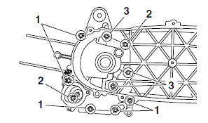
4. Install:
- Crankcase bolts
 Crankcase bolt
10 Nm (1.0 m*kgf, 7.2 ft*lbf)
Crankcase bolt
10 Nm (1.0 m*kgf, 7.2 ft*lbf)
TIP
Tighten the crankcase bolts in stages and in a crisscross pattern.
- M6 × 110 mm (4.33 in) bolts: "1"
- M6 × 80 mm (3.15 in) bolts: "2"
- M6 × 70 mm (2.76 in) bolts: "3"
5. Install:
- Oil filter element cover "1"
 Oil filter element cover
10 Nm (1.0 m*kgf, 7.2 ft*lbf)
Oil filter element cover
10 Nm (1.0 m*kgf, 7.2 ft*lbf)
TIP
Be sure to face the "  " mark "a"
on the oil filter
element cover in the direction shown in the illustration.
" mark "a"
on the oil filter
element cover in the direction shown in the illustration.
See also:
 Yamaha XMAX YP125R - Service manual > Oil pump (YP125R)
Removing the oil pump Checking the oil pump 1. Check: Oil pump drive gear Oil pump driven gear Oil pump housing Oil pump housing cover
Yamaha XMAX YP125R - Service manual > Engine removal (YP250R)
Removing the muffler and exhaust pipe Disconnecting the leads and hoses Disconnecting the leads and hoses Removing the engine


