 Suzuki Burgman 400 - Service manual > Drive V-belt Inspection
Perform the inspection in the following procedures:
1) Remove the drive V-belt. Refer to "V-belt Type Continuously Variable Automatic Transmission Removal and Installation".
2) Inspect the following items and if any defects are found, replace the drive V-belt with a new one.
- Check for grease or oil sticking on the drive V-belt.
- Check for crack or other damage on the surface contacted by the face.
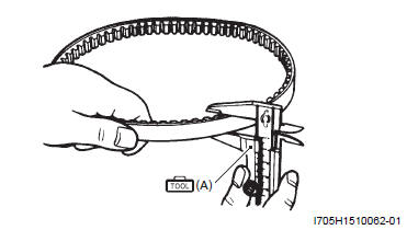
- Measure drive V-belt width using the vernier calipers.
Special tool (A): 09900-20101 (Vernier calipers (1/15 mm, 150 mm) )
Drive V-belt width
Standard: 25.1 mm (0.99 in)
Service limit: 24.1 mm (0.95 in)
3) After inspection, install the drive V-belt. Refer to "Vbelt Type Continuously Variable Automatic Transmission Removal and Installation".
Cooling Fan Filter Inspection
Perform the inspection in the following procedures:
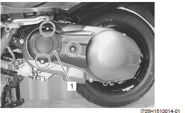
1) Remove the cooling fan duct (1).
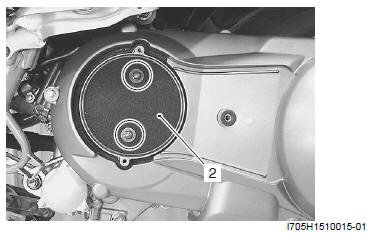
2) Remove the cooling fan filter (2).
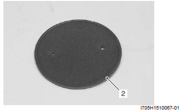
3) Check for dirt, clogging and damage on belt cooling filter (2) and if any, replace the filter with a new one.
4) After inspection, install the belt cooling filter and belt cooling duct.
Inner Clutch Cover Bearing Inspection
Inspect the play of the inner clutch cover bearings by finger while they are in the inner clutch cover. Rotate the inner race by finger to inspect for abnormal noise and smooth rotation. Replace the bearing in the following procedures if there is anything unusual. Refer to "Inner Clutch Cover Bering Removal and Installation".
Inner Clutch Cover Bering Removal and Installation
Removal
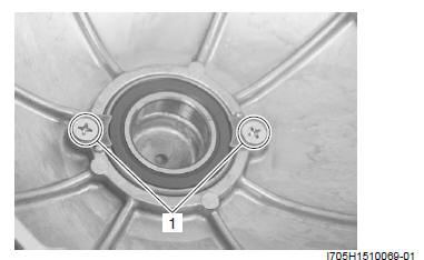
1) Remove the inner clutch cover. Refer to "V-belt Type Continuously Variable Automatic Transmission Removal and Installation".
2) Remove the bearing retainers (1).
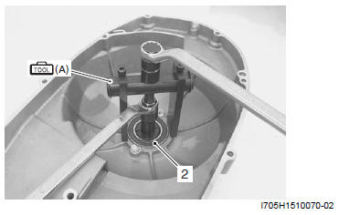
3) Remove the bearing (2) using the special tool.
Special tool (A): 09921-20240 (Bearing remover set)
Installation
Install the bearing in the reverse order of removal. Pay attention to the following points:
! CAUTION The removed bearing must be replaced with the new ones.
- Apply grease to the bearing and inner clutch cover side.
 : Grease
99000-25010 (SUZUKI SUPER GREASE A or equivalent)
: Grease
99000-25010 (SUZUKI SUPER GREASE A or equivalent)
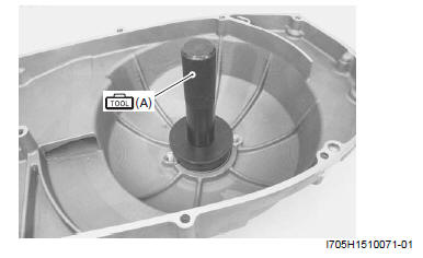
- Install the bearing to the inner clutch cover using the special tool.
! CAUTION When installing the bearing, stamped mark on the bearing must face outside.
Special tool (A): 09913-70210 (Bearing installer set)
Movable Drive Face Component
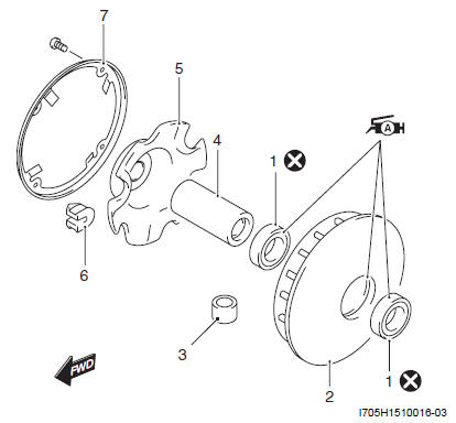
- Oil seal
- Movable drive face
- Roller
- Spacer
- Movable drive plate
- Damper
- Movable drive face cover
: Apply grease.
 : Do not reuse.
Movable Drive Face Disassembly and Assembly
Refer to "V-belt Type Continuously Variable Automatic Transmission Removal and Installation" and "Movable Drive Face Component".
Disassembly
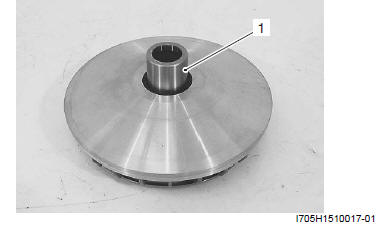
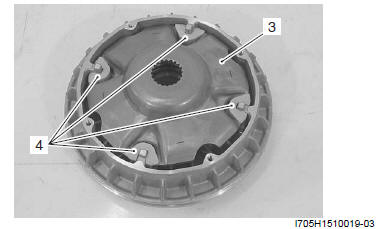
1) Remove the spacer (1).
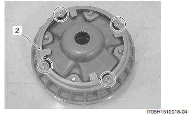
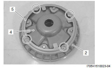
2) Remove the movable drive face cover (2).
3) Remove the movable drive plate (3) and dampers (4).
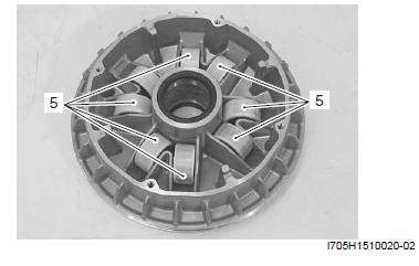
4) Remove the rollers (5).
Assembly
Refer to "Movable Drive Face Parts Inspection".
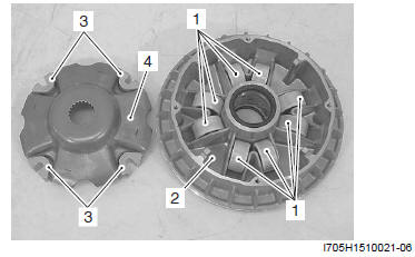
1) Assemble the rollers (1) to the movable drive face (2).
NOTE Check that the roller inside the movable drive face is not running off the groove.
2) Assemble the damper (3) to the movable drive plate (4).
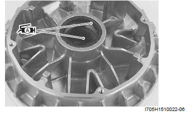
3) Fill the grease into the sliding face of movable drive face.
4) Apply the grease lightly on the oil seal lip.
: Grease
99000-25010 (SUZUKI SUPER GREASE A or equivalent)
! CAUTION Excess grease should be wiped off.
5) Assemble the movable drive plate (4) to movable drive face (2).
6) Assemble the movable drive face cover (5).
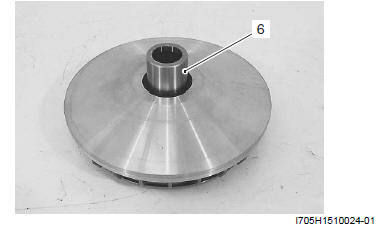
7) Assemble the spacer (6).
See also:
 Suzuki Burgman 400 - Service manual > Clutch and movable driven face
1) Hold the clutch housing using the special tool and remove the clutch housing nut (1) and remove the clutch housing (2). Special tool (A): 09930-40113 (Rotor holder)


