 Suzuki Burgman 400 - Service manual > Generator Removal and Installation
Removal
1) Drain engine oil.
2) Remove the side leg shield. Refer to "Side Leg Shield Removal and Installation".
3) Remove the generator cover. Refer to "CKP Sensor Removal and Installation".
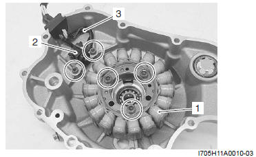
4) Remove the generator stator (1), CKP sensor (2) and lead wire guide (3).
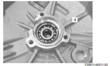
5) Remove the snap ring (4).
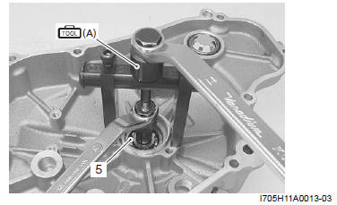
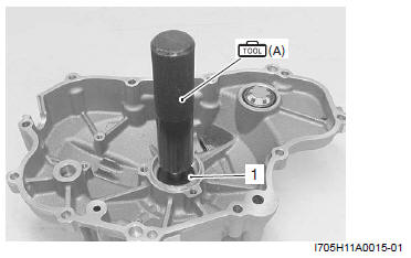
6) Remove the bearing (5) using the special tool.
Special tool (A): 09921-20240 (Bearing remover set)
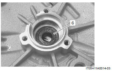
7) Remove the oil seal (6).
Installation
Install the generator in the reverse order of removal. Pay attention to the following points:
- Install the oil seal (1) using the special tool.
Special tool (A): 09913-75821 (Bearing installer)
! CAUTION
- Install the oil seal with the marked code toward outside.
- Replace the oil seal with a new one.
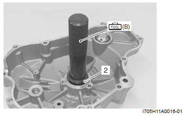
- Install the bearing (2) using the special tool.
Special tool (B): 09913-70210 (Bearing installer set)
! CAUTION Replace the bearing with a new one.
- Install the snap ring.
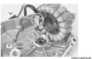
- Install the generator stator into the generator cover.
! CAUTION Engage the convex part "A" on the starter into the notch "B" on the generator cover.
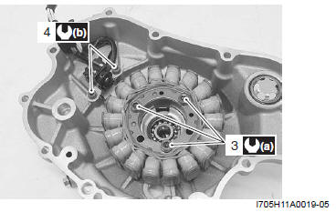
- Tighten the generator stator bolts (3) to the specified torque.
Tightening torque
Generator stator bolt (a): 11 N*m (1.1 kgf-m, 8.0 lb-ft)
- Tighten the CKP sensor bolts (4) to the specified torque.
Tightening torque
CKP sensor bolt (b): 6 N*m (0.6 kgf-m, 4.5 lb-ft)
- Install the generator cover.
! CAUTION Replace the gasket with a new one.
- Install the muffler. Refer to "Exhaust Pipe / Muffler Removal and Installation".
- Install the side leg shield. Refer to "Side Leg Shield Removal and Installation".
Battery Components
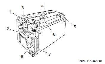
- Upper cover breather
- Cathode plates
- Stopper
- Filter
- Terminal
- Safety valve
- Anode plates
- Separator (Fiberglass)
Battery Initial Charging
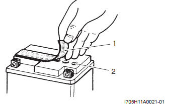
Filling Electrolyte
1) Remove the aluminum tape (1) which seals the battery filler holes (2).
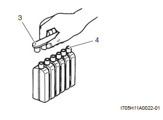
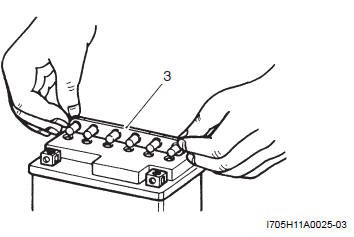
2) Remove the caps (3) from the electrolyte container.
NOTE
- Do not remove or pierce the sealed areas (4) of the electrolyte container.
- After completely filling the battery with electrolyte, use the caps (3) from the electrolyte container to seal the battery filler holes.
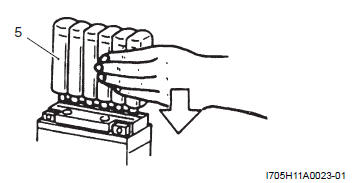
3) Insert the nozzles of the electrolyte container (5) into the electrolyte filler holes of the battery.
4) Hold the electrolyte container firmly so that it does not fall.
5) Do not allow any of the electrolyte to spill.
6) Make sure the air bubbles (6) rise to the top of each electrolyte container and leave the electrolyte container in this position for more than 20 minutes.
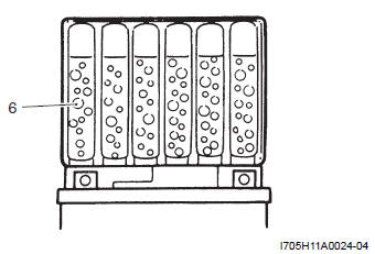
NOTE If air bubbles do not rise from any one of the filler ports, tap the bottom of the electrolyte container two or three times.
Never remove the electrolyte container from the battery while there is still electrolyte in the container.
7) After the electrolyte container is completely empty, remove it from the battery and wait about 20 minutes.
8) Insert the caps (3) firmly into the filler holes, so that the top of the caps do not protrude above the upper surface of the top cover of the battery.
! CAUTION
- Never use anything except the specified battery.
- Once install the caps to the battery, do not remove the caps.
- Do not tap the caps with a hammer when installing them.
CORRECT
INCORRECT
Initial Changing
1) Measure the battery voltage using multi circuit tester.
2) The tester should indicate more than 12.5 - 12.6 V (DC) as shown in the figure.
3) If the battery voltage is lower than the specification, charge the battery with a battery charger. Refer to "Battery Recharging ".
! CAUTION Do not remove the caps on the battery top while charging.
NOTE Initial charging for a new battery is recommended if two years have elapsed since the date of manufacture.
Battery Visual Inspection
Inspect the battery visual in the following procedures:
1) Visually inspect the surface of the battery container.
2) If any signs of cracking or electrolyte leakage from the sides of the battery have occurred, replace the battery with a new one.
3) If the battery terminals are found to be coated with rust or an acidic white powdery substance, clean the battery terminals with sandpaper.
See also:
 Suzuki Burgman 400 - Service manual > Generator Coil Resistance Inspection
Inspect the generator coil resistance in the following procedures: 1) Disconnect the generator coupler (1).
Suzuki Burgman 400 - Service manual > Battery Recharging
! CAUTION When recharging the battery, remove the battery from the motorcycle. NOTE While recharging, do not remove the caps on the top of the battery.


