 Suzuki Burgman 400 - Service manual > Precautions
Engine Cooling System Warning
! WARNING
- You can be injured by scalding fluid or steam if you open the
radiator cap when the engine is hot.
After the engine cools, wrap a thick cloth around cap and carefully remove the cap by turning it a quarter turn to allow pressure to escape and then turn the cap all the way off.
- The engine must be cool before servicing the cooling system.
- Coolant is harmful:
- If it comes in contact with skin or eyes, flush with water.
- If swallowed accidentally, induce vomiting and call physician immediately.
- Keep it away from children.
General Description
Cooling System Description
The engine is cooled by the forced circulation of engine coolant, using a high-capacity, centrifugal water pump, through water jackets formed in the cylinder and cylinder head, and through the radiator. The tube-and-fin type radiator is made of aluminum, which is characterized by lightness in weight and good heat dissipation.
A wax-pellet type thermostat is used to regulate the flow of engine coolant through the radiator. As the coolant temperature rises to about 88 ºC (190 ºF) the thermostat valve unseats and a normal coolant flow is established.
At about 100 ºC (212 ºF) the thermostat becomes completely open and, as a result, heat is released to the atmosphere through the radiator core.
Engine Coolant Description
At the time of manufacture, the cooling system is filled with a 50:50 mixture of distilled water and ethylene glycol anti-freeze. This 50:50 mixture will provide the optimum corrosion protection and excellent heat protection, and will protect the cooling system from freezing at temperatures above -31 ºC (-24 ºF).
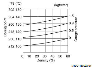
If the vehicle is to be exposed to temperatures below - 31 ºC (-24 ºF), this mixing ratio should be increased up to 55% or 60% according to the figure.
Anti-freeze Proportioning Chart
! CAUTION
- Use a high quality ethylene glycol base anti-freeze, mixed with distilled water. Do not mix an alcohol base anti-freeze and different brands of anti-freeze.
- Do not put in more than 60% anti-freeze or less than 50%. (Refer to Fig. 1 and 2.)
50% Engine coolant including reserve tank capacity
Engine Coolant Capacity
Fig. 1: Engine coolant density-freezing point curve
Fig. 2: Engine coolant density-boiling point curve
Cooling Fan Thermo-Switch Description
The cooling fan is secured behind the radiator by three bolts and is automatically controlled by the thermo-switch. The thermo-switch remains open when the temperature of the engine coolant is low, but closes when the temperature reaches approximately 98 ºC (208 ºF) setting the cooling fan in motion.
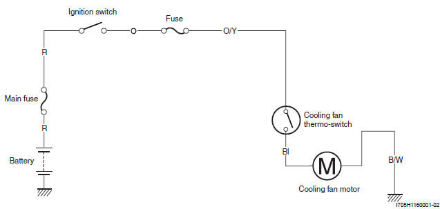
Bl: Blue
R: Red
O: Orange
O/Y: Orange with Yellow tracer
B/W: Black with White tracer
Engine Coolant Temperature Sensor Description
The following circuit diagram shows the electrical wiring for the thermometer. The major components are ECT sensor in contact with coolant, and engine coolant temperature meter.
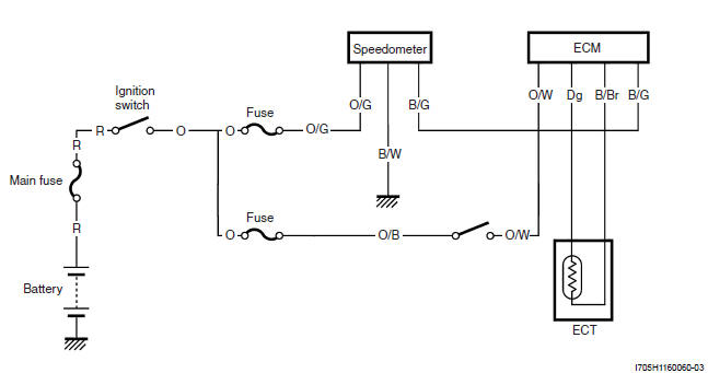
Dg: Dark green
O: Orange
R: Red
B/Br: Black with Brown tracer
B/G: Black with Green tracer
O/B: Orange with Black tracer
O/G: Orange with Green tracer
O/W: Orange with White tracer
P/W: Pink with White tracer
Schematic and Routing Diagram
Cooling Circuit Diagram
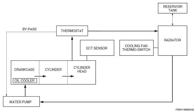
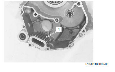
Oil cooler (1) is located inside the crankcase.
The engine oil is cooled by engine coolant, which is circulated through inside core of oil cooler.
Radiator Hose Routing Diagram
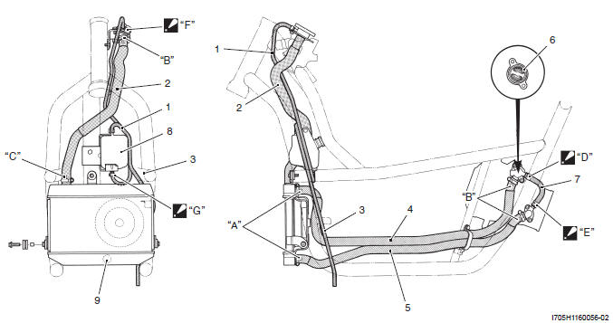
- Reservoir tank inlet hose
- Conduction hose
- Reservoir tank overflow hose
- Radiator inlet hose
- Radiator outlet hose
- Thermostat
- Water by-pass hose
- Reservoir tank
- Cooling fan thermo-switch
- Yellow making
- White marking
- Pink marking
- The clamp end should face to engine side.
- The clamp end should face forward.
- The clamp end should face downward.
- The clamp end should face to left side.
Component Location
Engine Cooling System Components Location
Refer to "Electrical Components Location".
Diagnostic Information and Procedures
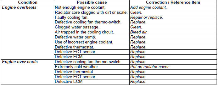
Engine Cooling Symptom Diagnosis
See also:
 Suzuki Burgman 400 - Service manual > Cooling Circuit, Radiator
Cooling Circuit Inspection ! WARNING Do not open the radiator cap when the engine is hot, as you may be injured by escaping hot liquid or vapor. When removing the radiator cap tester, put a rag on the filler to prevent the engine coolant from spraying out.


