 Suzuki Burgman 400 - Service manual > Precautions, Wiring Systems
Precautions for Electrical System
Refer to "General Precautions".
Component Location
Electrical Components Location
Refer to "Electrical Components Location".
Wiring Systems
Schematic and Routing Diagram
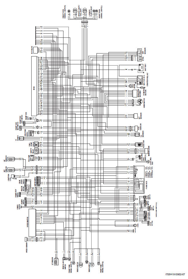
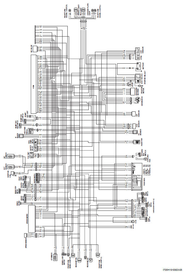
Wiring Diagram
Refer to "Wire Color Symbols".
E-02, 19, 24, 54
E-03, 28, 33
Wiring Harness Routing Diagram
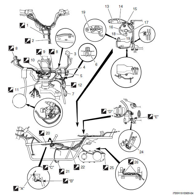
- Clamp
: Clamp the handlebar switch lead wires (LH and RH), Brake hoses (Front and Rear) and throttle cables. - 2. Clamp
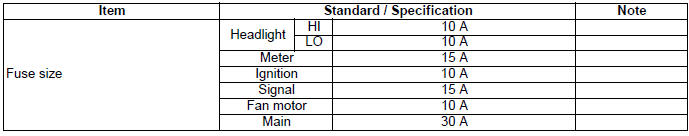
: Clamp with marking. - Fuse box
- Key-less control unit (For 000 only)
- ECM
- White tape
- Regulator/rectifier read wire
- Clamp
: Clamp the wiring harness and battery (+) lead wire. - Clamp
: Clamp the left and right handlebar switch lead wires. - Clamp
: Clamp the wiring harness, battery (+) lead wire and starter relay lead wire. - Clamp : Clamp the wiring harness and battery (-) lead wire.
- Clamp
: Clamp the regulator/rectifier lead wire, battery (+) and (-) lead wires. - STVA
- STP sensor
- TP sensor
- ISC valve
- Fuel injector
- IAP sensor
- IAT sensor
- Clamp
: Clamp the wiring harness and battery (-) lead wire. - Side-stand switch
- Clamp
: Clamp the wiring harness, battery (-) and side-stand switch lead wire. - Clamp
: Clamp the wiring harness, battery (-) lead wire and generator lead wires. - Ignition coil
- Speed sensor
- Clamp
: Clamp the generator lead wires and HO2 sensor lead wire with no slack.
- Cut the surplus of clamp.
- Pass the lead wires through inside the cable guide.
- Pass the lead wires through outside the hoses.
- To IAT sensor.
- Pass the ignition coil lead wire through inside the water by-pass hose
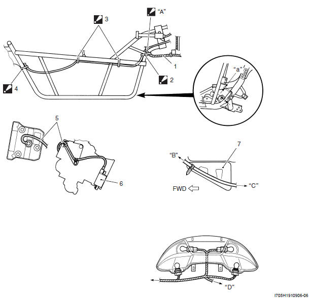
- Wiring harness
- Clamp
: Clamp the starter motor lead wire and wiring harness. - Clamp
: Clamp the starter motor lead wire and brake-lock cable. - Clamp
: Clamp the rear brake hose, brake-lock cable and starter motor lead wire. - High tension code
- Ignition coil
- Air cleaner
- Pass the wiring harness through front of seat lock cable.
- To IAT sensor
- To main harness
- To license light
- 2.3 mm (0.08 - 0.12 in)
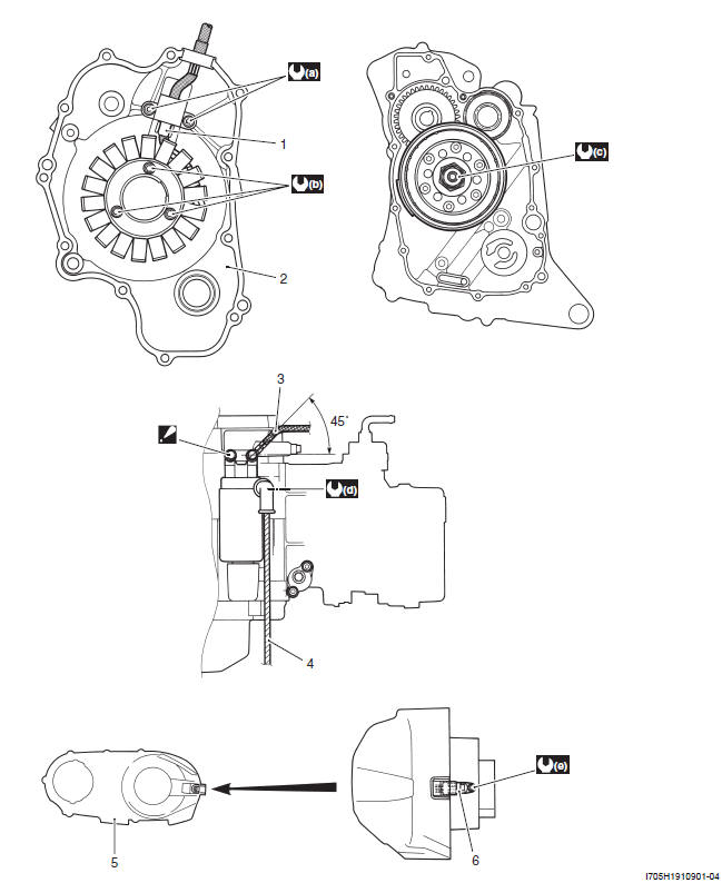
- CKP sensor
- Generator cover
- Battery (-) lead wire
- Starter motor lead wire
- Outer clutch cover
- Speed sensor
 : Tighten the rear
side bolt first.
: Tighten the rear
side bolt first.
- : 6 N*m (0.6 kgf-m, 4.5 lb-ft)
- : 11 N*m (1.1 kgf-m, 8.0 lb-ft)
- : 160 N*m (16.0 kgf-m, 111.5 lb-ft)
- : 3 N*m (0.3 kgf-m, 2.0 lb-ft)
- : 10 N*m (1.0 kgf-m, 7.0 lb-ft)
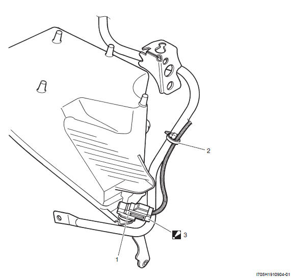
- Ambient air temperature sensor
- Clamp
- Coupler
: Do not attempt to disconnect the coupler from the sensor.
Specifications
Service Data
Electrical
Unit: mm (in)
Tightening Torque Specifications
NOTE The specified tightening torque is also described in the following.
Reference: For the tightening torque of fastener not specified in this section, refer to "Tightening Torque Specifications".


