 Yamaha XMAX YP125R - Service manual > Removing the valves
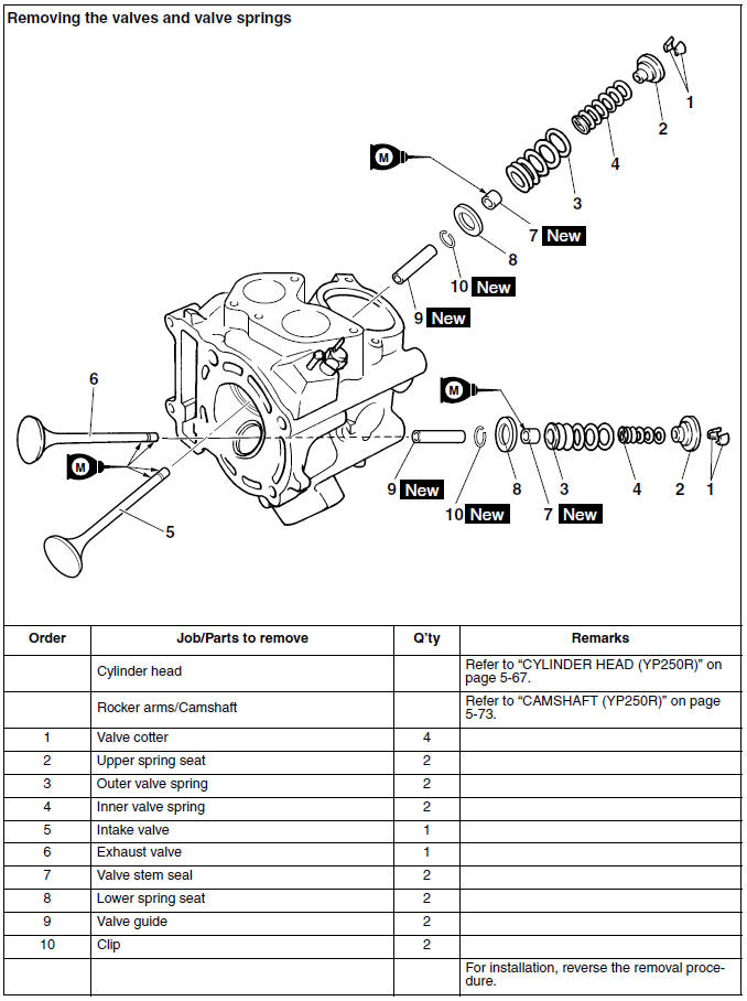
Removing the valves and valve springs
The following procedure applies to all of the valves and related components.
TIP
Before removing the internal parts of the cylinder head (e.g., valves, valve springs, valve seats), make sure the valves properly seal.
1. Check:
- Valve sealing
Leakage at the valve seat → Check the valve face, valve seat, and valve seat width.
a. Pour a clean solvent "a" into the intake and exhaust ports.
b. Check that the valves properly seal.
TIP
There should be no leakage at the valve seat "1".
2. Remove:
- Valve cotters "1"
TIP
Remove the valve cotters by compressing the valve spring with the valve spring compressor and the valve spring compressor attachment "2".
 Valve spring compressor 90890-04019 YM-04019
Valve spring compressor attachment 90890-04108
Valve spring compressor adapter 22 mm YM-04108
3. Remove:
- Upper spring seat "1"
- Outer valve spring "2"
- Inner valve spring "3"
- Valve "4"
- Valve stem seal "5"
- Lower spring seat "6"
TIP
Identify the position of each part very carefully so that it can be reinstalled in its original place.
Checking the valves and valve guides
The following procedure applies to all of the valves and valve guides.
1. Measure:
- Valve-stem-to-valve-guide clearance
Out of specification → Replace the valve guide.
Valve-stem-to-valve-guide clearance =
Valve guide inside diameter "a" -
Valve stem diameter "b"
 Valve-stem-to-valve-guide clearance (intake) 0.010-0.037 mm (0.0004-0.0015 in)
Limit 0.080 mm (0.0031 in)
Valve-stem-to-valve-guide clearance (exhaust) 0.025-0.052 mm (0.0010-0.0020 in)
Limit 0.100 mm (0.0039 in)
2. Replace:
- Valve guide
TIP
To ease valve guide removal and installation, and to maintain the correct fit, heat the cylinder head to 100 ºC (212 ºF) in an oven.
a. Remove the valve guide with the valve guide remover "1".
b. Install a new clip and new valve guide with the valve guide installer "2" and valve guide remover "1".
c. After installing the valve guide, bore the valve guide with the valve guide reamer "3" to obtain the proper valve-stem-to-valve-guide clearance.
TIP
After replacing the valve guide, reface the valve seat.
 Valve guide remover (ø6) 90890-04064
Valve guide remover (6.0 mm) YM-04064-A
Valve guide installer (ø6) 90890-04065
Valve guide installer (6.0 mm) YM-04065-A
Valve guide reamer (ø6) 90890-04066
Valve guide reamer (6.0 mm) YM-04066
3. Eliminate:
- Carbon deposits (from the valve face and valve seat)
4. Check:
- Valve face
Pitting/wear → Grind the valve face.
- Valve stem end
Mushroom shape or diameter larger than the body of the valve stem → Replace the valve.
5. Measure:
- Valve margin thickness "a"
Out of specification → Replace the valve.
 Valve margin thickness D (intake) 0.80-1.20 mm (0.0315-0.0472 in)
Valve margin thickness D (exhaust) 0.80-1.20 mm (0.0315-0.0472 in)
6. Measure:
- Valve stem runout
Out of specification → Replace the valve.
TIP
- When installing a new valve, always replace the valve guide.
- If the valve is removed or replaced, always replace the valve stem seal.
 Valve stem runout 0.010 mm (0.0004 in)
Checking the valve seats
The following procedure applies to all of the valves and valve seats.
1. Eliminate:
- Carbon deposits (from the valve face and valve seat)
2. Check:
- Valve seat Pitting/wear → Replace the cylinder head.
3. Measure:
- Valve seat width "a"
Out of specification → Replace the cylinder head.
 Valve seat width C (intake) 0.90-1.10 mm (0.0354-0.0433 in) Limit 1.6 mm (0.06 in)
Valve seat width C (exhaust) 0.90-1.10 mm (0.0354-0.0433 in)
Limit 1.6 mm (0.06 in)
a. Apply Mechanic's blueing dye (Dykem) "b" onto the valve face.
b. Install the valve into the cylinder head.
c. Press the valve through the valve guide and onto the valve seat to make a clear impression.
d. Measure the valve seat width.
TIP
Where the valve seat and valve face contacted one another, the blueing will have been removed.
4. Lap:
- Valve face
- Valve seat
TIP
After replacing the cylinder head or replacing the valve and valve guide, the valve seat and valve face should be lapped.
a. Apply a coarse lapping compound "a" to the valve face.
NOTICE
Do not let the lapping compound enter the gap between the valve stem and the valve guide.
b. Apply molybdenum disulfide oil onto the valve stem.
c. Install the valve into the cylinder head.
d. Turn the valve until the valve face and valve seat are evenly polished, and then clean off all of the lapping compound.
TIP
For the best lapping results, lightly tap the valve seat while rotating the valve back and forth between your hands.
e. Apply a fine lapping compound to the valve face and repeat the above steps.
f. After every lapping procedure, be sure to clean off all of the lapping compound from the valve face and valve seat.
g. Apply Mechanic's blueing dye (Dykem) "b" onto the valve face.
h. Install the valve into the cylinder head.
i. Press the valve through the valve guide and onto the valve seat to make a clear impression.
j. Measure the valve seat width again. If the valve seat width is out of specification, reface and lap the valve seat.
See also:
 Yamaha XMAX YP125R - Service manual > Checking the valve springs
The following procedure applies to all of the valve springs. 1. Measure: Valve spring free length "a" Out of specification → Replace the valve spring.


