 PIAGGIO Beverly 300ie - Service manual > Tachometer
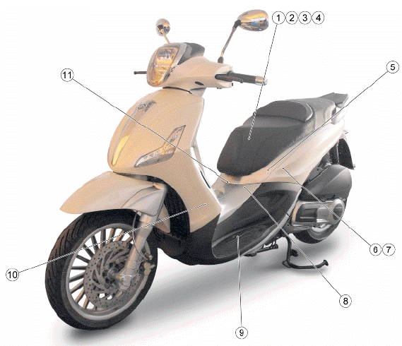
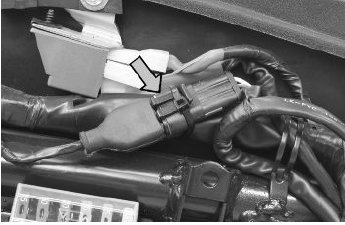
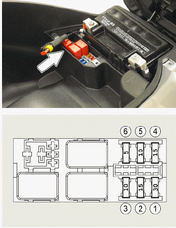
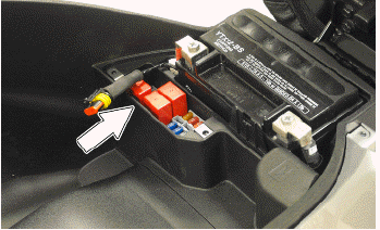
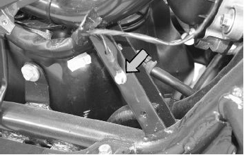
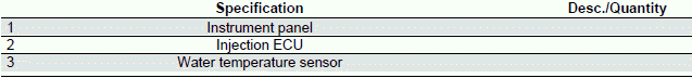
COMPONENT LAYOUT
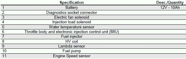
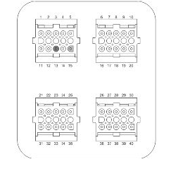
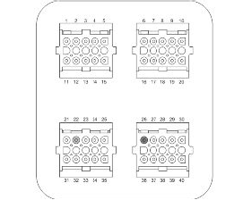
With wiring disconnected from the control unit and connected to the system, check that the sensor resistance between pins 13 - 15 is between 100 and 150 Ohm at an engine temperature of approximately 20º
Disconnect the fuel pipe connector. Start up the engine and wait for it to stop. With the wiring connected to the control unit and system try to start up the engine and check that the voltage between pins 13 and 15 is around 2.8 V
With the interface cable harness disconnected from the control unit, check continuity between pin 13 and the red cable of the engine speed sensor connector and between pin 15 and the brown cable of the engine speed sensor connector
With the interface wiring and rpm sensor connector disconnected from the control unit, check that the Red and Brown cables (pin 13 - 15) are isolated from each other and insulated from the ground.
Specific tooling
020481Y Control unit interface wiring
020331Y Digital multimeter
HT coil
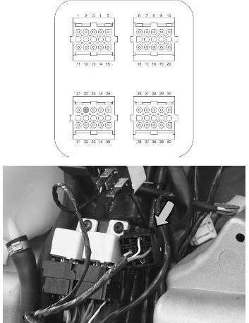
INJECTION LOADS
The ignition system is integrated with the injection and it is a high-efficiency inductive type ignition.
The control unit controls two important parameters:
- Ignition advance
This is optimised from moment to moment in accordance with the engine revs, engine load, temperature and environmental pressure.
With idle engine, it is optimised to obtain the stabilisation of the speed at 1450 +- 50 R/1'.
- Magnetisation time
The coil magnetisation time is controlled by the control unit. The ignition power is increased during the engine start-up phase.
The injection system recognises the four-stroke cycle so the ignition is only commanded in the compression phase.
Specific tooling
020331Y Digital multimeter
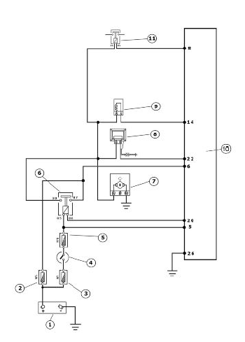
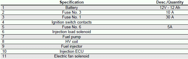
Check function of fuses No. 3 and 6 for the ECU and injection load solenoid.
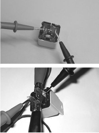
Check the efficiency of the injection load solenoid.
Check the resistance of the energising coil between pins 86 and 85: 40 to 80 Ohm
Apply a voltage of 12V to pins 86 and 85; make sure that there is continuity between pins 30 and 87 of the relay.
WARNING
TO INDICATE THE RELAY OF THE DESIRED FUNCTION, REFER TO THE PIN-CABLE COLOUR RELATIONSHIP WITH THE ATTACHED ELECTRIC SYSTEM DIAGRAM.
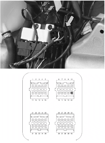
Check the power supply line of the injection load solenoid energising coil: after switching to "ON", make sure there is battery voltage, for 2 seconds, between the Red-White cable and the Black-Purple cable of the solenoid base. If there is not, check the continuity of the Red-White cable between the fuse box and the solenoid base and of the Black- Purple cable between the pin 20 of the control unit and the solenoid base.
N.B.
CONTINUITY TESTS MUST BE CARRIED OUT WITH THE COMPONENTS DISCONNECTED. (RELAYS, CONTROL UNIT, FUSES ETC.).
Check for continuous voltage between the grey/ black cable of the solenoid base and ground. If no voltage is measured, check continuity of the Grey/ Black cable between the fuse box (No. 3, 5A) and the solenoid base.
N.B.
CONTINUITY TESTS MUST BE CARRIED OUT WITH THE COMPONENTS DISCONNECTED. (RELAYS, CONTROL UNIT, FUSES ETC.).
Check there is voltage between pins 22 and 26 of the interface wiring for around two seconds when switching to "ON".
Check the resistance of the primary coil between pin 22 of the interface wiring and the green black cable of the injection load solenoid base with the control unit disconnected and the solenoid disconnected.
Resistance of the primary = 0.5 +- 8% Ohm
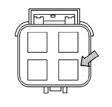
Coolant temperature sensor
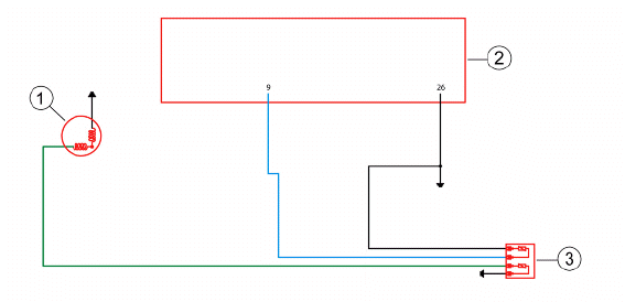
TEMPERATURE SENSOR
With the connector on the control unit side disconnected and the coolant temperature sensor connector connected, check that the resistance values between pin 9 and the ground lead correspond with the engine temperature.
20º = 2500 +- 100 Ω
80º = 308 +- 6 Ω
With the connector on the control unit side disconnected and the coolant temperature connector disconnected, check the insulation between the lightblue/ green cable and ground lead.
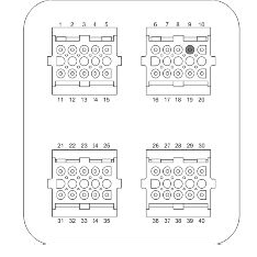
With the connector on the control unit side disconnected and the coolant temperature connector disconnected, check the continuity between pin 9 of the interface cable harness and the light-blue/ green cable of the connector.
Specific tooling
020481Y Control unit interface wiring
020331Y Digital multimeter
See also:
 PIAGGIO Beverly 300ie - Service manual > Zeroing the throttle
Resetting the throttle valve position signal (TPS reset) The MIU control unit is supplied with a throttle valve position sensor that is pre-calibrated. Pre-calibration entails regulating the minimum opening of the throttle valve to obtain a certain flow of air under pre-set reference conditions.


