 Suzuki Burgman 400 - Service manual > Water Pump
Water Pump Components
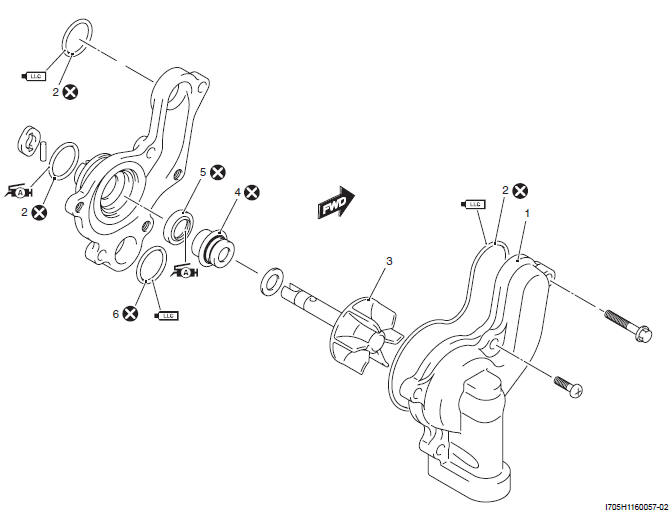
- Water pump cover
- O-ring
- Impeller
- Mechanical seal
- Oil seal
- Mechanical seal ring
 : Apply grease.
 : Apply engine
coolant.
: Apply engine
coolant.
 : Do not reuse.
Water Pump Construction
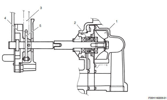
- Impeller
- Mechanical seal
- Oil pump drive chain
- Oil pump
- Oil pump driven sprocket
Water Pump Removal and Installation
Removal
1) Remove the under cover. Refer to "Under Cover Removal and Installation".
2) Drain engine coolant. Refer to "Cooling System Inspection".
3) Drain engine oil. Refer to "Engine Oil and Filter Change".
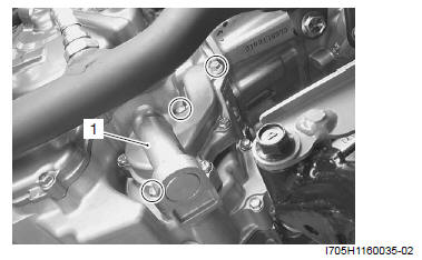
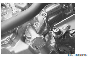
4) Remove the water pomp assembly (1).
Installation
Install the water pump assembly in the reverse order of removal. Pay attention to the following points:
! CAUTION Replace the O-rings with the new ones.
- Apply grease to the O-ring (1).
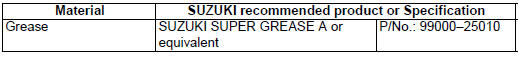
: Grease
99000-25010 (SUZUKI SUPER GREASE A or equivalent)
- Apply engine coolant to the O-rings (2).
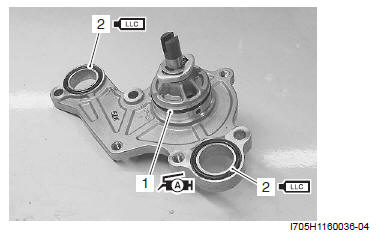
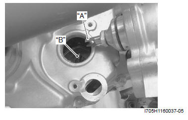
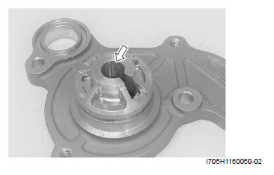
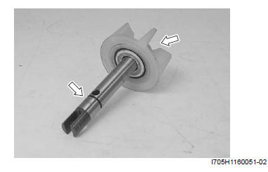
- Install the water pump assembly with the slot on the pump shaft end "A" securely engaged with the flat "B" on the oil pump shaft.
- Tighten the water pump mounting bolts to the specified torque.
Tightening torque
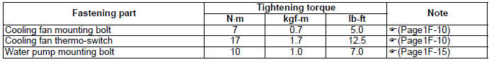
Water pump mounting bolt: 10 N*m (1.0 kgf-m, 7.0 lb-ft)
- Pour engine coolant. Refer to "Cooling System Inspection".
- Pour engine oil. Refer to "Engine Oil and Filter Change ".
- Bleed air from the cooling circuit. Refer to "Cooling System Inspection".
Water Pump Disassembly and Assembly
Refer to "Water Pump Removal and Installation".
Disassembly
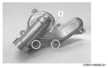
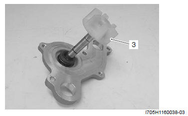
1) Remove the water pump cover (1).
2) Remove the O-rings and E-ring (2).
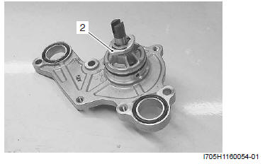
3) Remove the impeller (3) together with the water pump shaft.
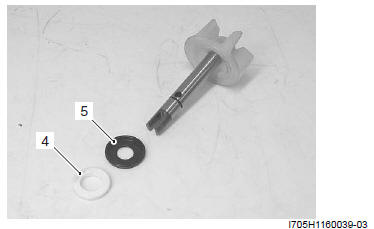
4) Remove the mechanical seal ring (4) and the rubber seal (5) from the impeller.
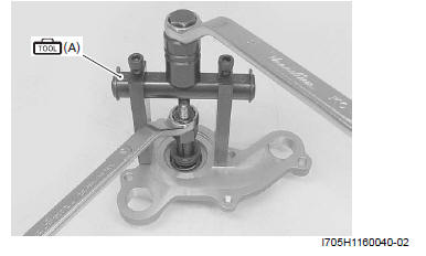
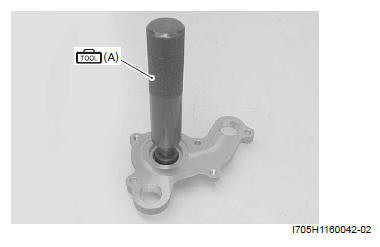
5) Remove the mechanical seal using the special tool.
NOTE If there is no abnormal condition, the mechanical seal removal is not necessary.
Special tool (A): 09921-20240 (Bearing remover set)
6) Remove the oil seal using a suitable bar.
! CAUTION The removed oil seal must be replaced with a new one.
NOTE If there is no abnormal condition, the oil seal removal is not necessary.
Assembly
Assemble the water pump in the reverse order of disassembly. Pay attention to the following points:
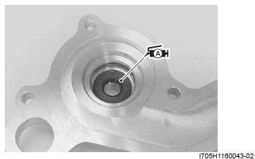
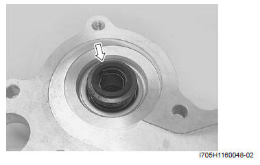
- Install the oil seal using the special tool.
Special tool (A): 09913-70210 (Bearing installer set)
NOTE The stamped mark on the oil seal faces mechanical seal side.
- Apply a small quantity of the super grease to the oil seal lip.
: Grease
99000-25010 (SUZUKI SUPER GREASE A or equivalent)
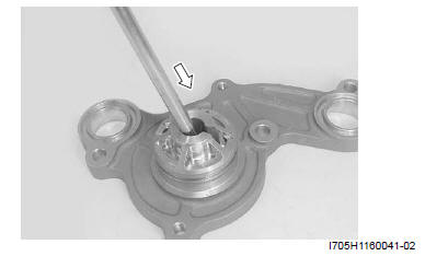
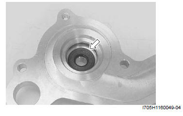
- Install a new mechanical seal using a suitable size socket wrench "A".
! CAUTION The removed mechanical seal must be replaced with a new one.
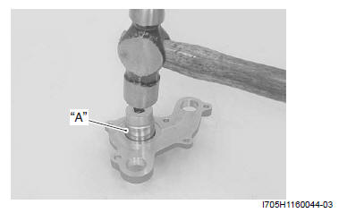
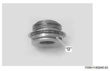
NOTE On the new mechanical seal, the sealer "B" has been applied.
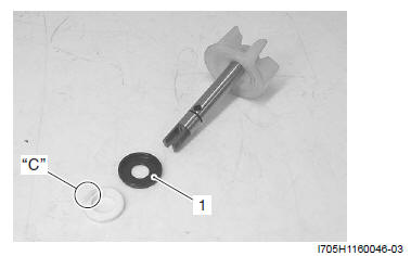
- Install the rubber seal (1) into the impeller.
- After wiping off the oily or greasy matter from the mechanical seal ring, install it into the impeller.
NOTE The paint marked side "C" of mechanical seal ring faces the rubber seal.
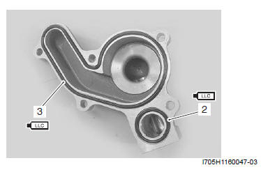
Install the new O-rings (2), (3).
! CAUTION Use the new O-rings to prevent engine coolant leakage.
NOTE Apply engine coolant to the O-ring (2) and (3).
: Grease
99000-25010 (SUZUKI SUPER GREASE A or equivalent)
Water Pump Related Parts Inspection
Refer to "Water Pump Disassembly and Assembly".
Mechanical Seal
Visually inspect the mechanical seal for damage, with particular attention given to the sealing face.
Replace the mechanical seal that shows indications of leakage.
Oil Seal
Visually inspect the oil seal for damage, with particular attention given to the lip.
Replace the oil seal that shows indications of leakage.
Impeller Shaft Journal
Visually inspect the journal for damage or scratch.
Replace the water pump body if necessary.
Impeller
Visually inspect the impeller and its shaft for damage.
Replace the impeller if necessary.
Specifications
Service Data
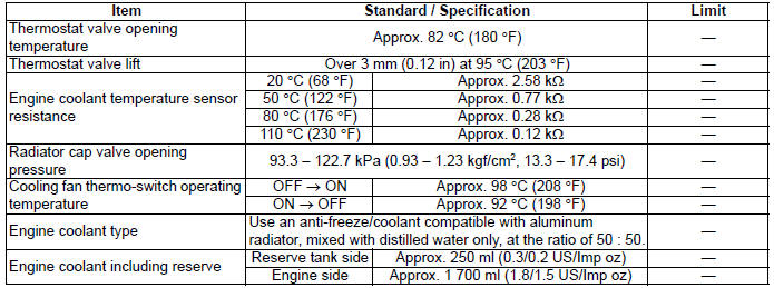
Thermostat + Radiator + Fan + Coolant
Tightening Torque Specifications
Reference: For the tightening torque of fastener not specified in this section, refer to "Tightening Torque Specifications".
Special Tools and Equipment
Recommended Service Material
Special Tool
 09900-25008
Multi-circuit tester set
09900-25008
Multi-circuit tester set
 09921-20240
Bearing remover set
09921-20240
Bearing remover set
 09913-70210
Bearing installer set
09913-70210
Bearing installer set
See also:
 Suzuki Burgman 400 - Service manual > Thermostat
Thermostat Removal and Installation Removal 1) Drain a small amount of engine coolant. Refer to "Cooling System Inspection". 2) Remove the air cleaner box. Refer to "Air Cleaner Box Removal and Installation".


