 Suzuki Burgman 400 - Service manual > Width Between Crankshaft Webs
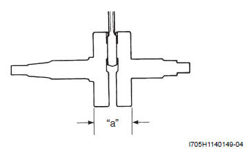
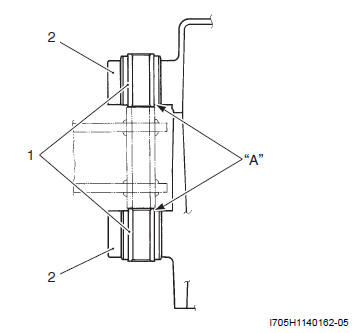
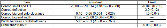
Measure the width between crankshaft webs "a".
Width between crankshaft webs "a"
Standard: 59.9 - 60.1 mm (2.358 - 2.366 in)
Bearing Inspection
Inspect the bearing in the following procedures:
1) Separate the crankcase. Refer to "Engine Bottom Side Assembly".
2) Rotate the bearing inner race by finger to inspect for abnormal play, noise and smooth rotation while the bearings are in the crankcase, if there is anything unusual, replace the bearing. Refer to "Bearing Removal and Installation".
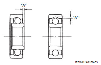
NOTE If abnormal noise does not occur, it is not necessary to remove the bearing.
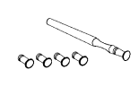
Bearing Removal and Installation
Removal
Separate the crankcase. Refer to "Engine Bottom Side Assembly".
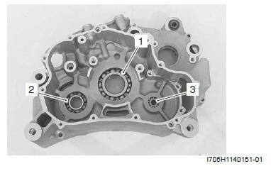
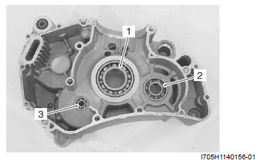
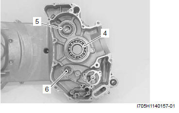
- Remove the bearing (1), (2) and (3) using the special tool.
Special tool : 09913-70210 (Bearing installer set)
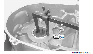
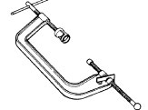
- Remove the oil seal using the special tool.
Special tool (A): 09913-50121 (Oil seal remover)
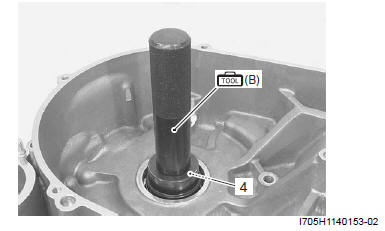
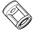
- Remove the bearing (4) using the special tool.
Special tool (B): 09913-70210 (Bearing installer set)
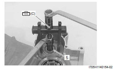
- Remove the bearing (5) using the special tool.
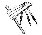
Special tool (C): 09921-20240 (Bearing remover set)
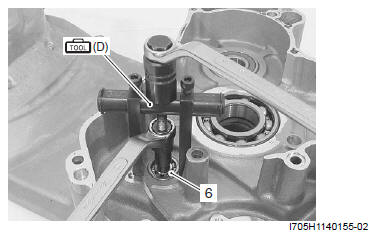
- Remove the bearing (6) using the special tool.
Special tool (D): 09921-20240 (Bearing remover set)
Installation
- Install the bearing (1), (2) and (3) using the special tool.
Special tool : 09913-70210 (Bearing installer set)
- Install the bearing (4), (5) and (6) using the special tool.
Special tool : 09913-70210 (Bearing installer set)
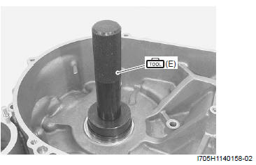
- Install the oil seal using the special tool.
Special tool (E): 09913-70210 (Bearing installer set)
! CAUTION Replace the removed oil seal with a new one.
Rear Suspension Mounting Bushing Removal and Installation
Removal
1) Separate the crankcase. Refer to "Engine Bottom Side Disassembly" and "Engine Bottom Side Assembly".
2) Using appropriate size steel tubes (1) and vise, remove the rear suspension mounting bushing (2) (LH and RH).
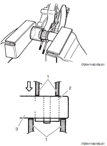
- Steel tube
- Bushing
- Crank case
Installation
1) Using an appropriate side steel tube and vise, press in the busing into the crankcase (LH and RH).
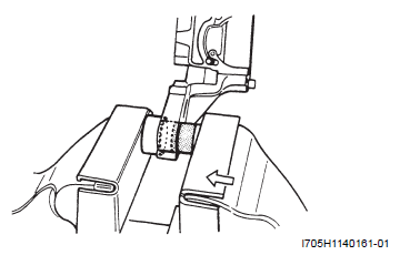
! CAUTION Bushing end "A" must be flush with the crankcase surface.
- Bushing
- Crank case
2) Assemble the crankcase. Refer to "Engine Bottom Side Disassembly" and "Engine Bottom Side Assembly".
Service Data
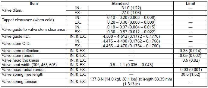
Valve + Valve Guide
Unit: mm (in)
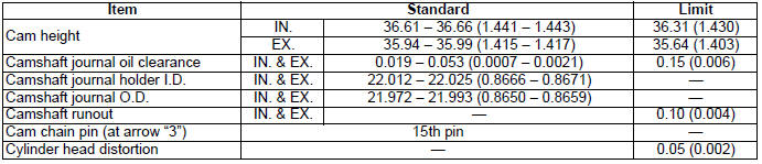
Camshaft + Cylinder Head
Unit: mm (in)
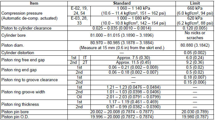
Cylinder + Piston + Piston Ring
Unit: mm (in)
Conrod + Crankshaft
Unit: mm (in)
Throttle Body
Tightening Torque Specifications
NOTE The specified tightening torque is also described in the following.
Reference: For the tightening torque of fastener not specified in this section, refer to "Tightening Torque Specifications".
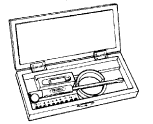
Special Tools and Equipment
Recommended Service Material
NOTE Required service material is also described in the following.
Special Tool
 09900-20102
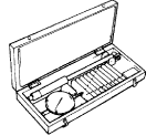
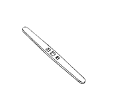
Vernier calipers (1/20 mm, 200 mm)
09900-20102
Vernier calipers (1/20 mm, 200 mm)
 09900-20202
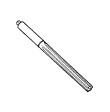
Micrometer (1/100 mm, 25 - 50 mm)
09900-20202
Micrometer (1/100 mm, 25 - 50 mm)
 09900-20204
Micrometer (75 - 100 mm)
09900-20204
Micrometer (75 - 100 mm)
 09900-20205
Micrometer (0 - 25 mm)
09900-20205
Micrometer (0 - 25 mm)
 09900-20508
Cylinder gauge set
09900-20508
Cylinder gauge set
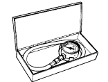
 09900-20602
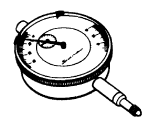
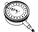
Dial gauge (1/1000 mm, 1 mm)
09900-20602
Dial gauge (1/1000 mm, 1 mm)
 09900-20605
Dial calipers (1/100 mm, 10 - 34 mm)
09900-20605
Dial calipers (1/100 mm, 10 - 34 mm)
 09900-20606
Dial gauge (1/100 mm)
09900-20606
Dial gauge (1/100 mm)
 09900-20607
Dial gauge (1/100 mm, 10 mm)
09900-20607
Dial gauge (1/100 mm, 10 mm)
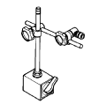 09900-20701
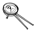
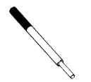
Magnetic stand
09900-20701
Magnetic stand
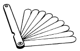 09900-20803
Thickness gauge
09900-20803
Thickness gauge
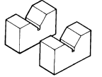 09900-21304
V-block (100 mm)
09900-21304
V-block (100 mm)
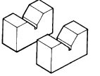 09900-21303
V-block (75 mm)
09900-21303
V-block (75 mm)
 09900-22301
Plastigauge (0.025 - 0.076 mm)
09900-22301
Plastigauge (0.025 - 0.076 mm)
 09900-22403
Small bore gauge (18 - 35 mm)
09900-22403
Small bore gauge (18 - 35 mm)
 09910-32812
Crankshaft installer
09910-32812
Crankshaft installer
 09910-32870
Crankshaft installer attachment
09910-32870
Crankshaft installer attachment
 09913-10750
Compression gauge adapter
09913-10750
Compression gauge adapter
 09913-50121
Oil seal remover
09913-50121
Oil seal remover
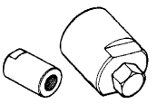
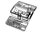 09913-70210
Bearing installer set
09913-70210
Bearing installer set
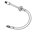
 09915-64512
Compression gauge
09915-64512
Compression gauge
 09916-10911
Valve lapper set
09916-10911
Valve lapper set
 09916-14510
Valve spring compressor
09916-14510
Valve spring compressor
 09916-14530
Valve spring compressor attachment
09916-14530
Valve spring compressor attachment
 09916-33210
Valve guide reamer (4.5 mm)
09916-33210
Valve guide reamer (4.5 mm)
 09916-34542
Reamer handle
09916-34542
Reamer handle
 09916-34561
Valve guide reamer (11.3 mm)
09916-34561
Valve guide reamer (11.3 mm)
 09916-43210
Valve guide remover/ installer
09916-43210
Valve guide remover/ installer
 09916-53330
Attachment
09916-53330
Attachment
 09916-84511
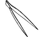
Tweezers
09916-84511
Tweezers
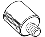
 09919-28610
Sleeve protector
09919-28610
Sleeve protector
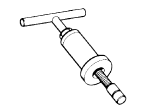
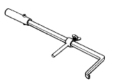
 09920-13120
Crankcase separating tool
09920-13120
Crankcase separating tool
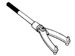
 09921-20240
Bearing remover set
09921-20240
Bearing remover set
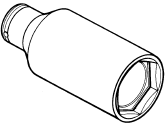 09922-21410
Long socket (46 mm)
09922-21410
Long socket (46 mm)
 09930-31921
Rotor remover
09930-31921
Rotor remover
 09930-40113
Rotor holder
09930-40113
Rotor holder
See also:
 Suzuki Burgman 400 - Service manual > Cam Chain Tensioner
Cam Chain Tensioner Inspection Inspect the cam chain tensioner in the following procedures: 1) Remove the cam chain tensioner. Refer to "Engine Bottom Side Disassembly".
Suzuki Burgman 400 - Service manual > Engine Lubrication System
Precautions Precautions for Engine Oil Refer to "Fuel / Oil / Engine Coolant Recommendation". Schematic and Routing Diagram


