 Suzuki Burgman 400 - Service manual > Engine Lubrication System
Precautions
Precautions for Engine Oil
Refer to "Fuel / Oil / Engine Coolant Recommendation".
Schematic and Routing Diagram
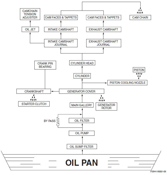
Engine Lubrication System Chart Diagram
Engine Lubrication Circuit Diagram
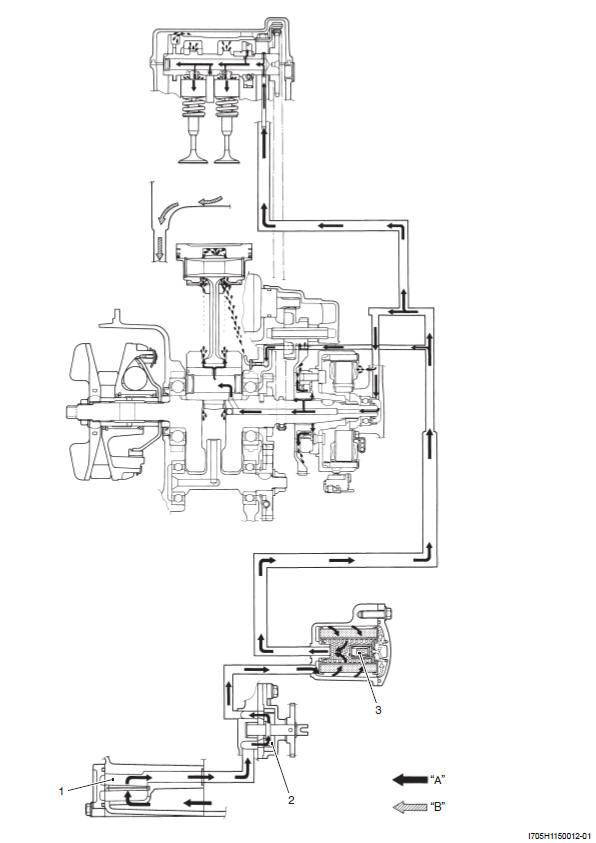
- Oil sump filter
- Oil pump
- Oil filter
- Lubrication oil
- Returned oil
Diagnostic Information and Procedures
Engine Lubrication Symptom Diagnosis
Oil Pressure Check
Check the engine oil pressure periodically. This will give a good indication of the condition of the moving parts.
NOTE Before checking the oil pressure, check the following.
- Oil level (Refer to "Engine Oil and Filter Change")
- Oil leaks (If leak is found, repair it.)
- Oil quality (If oil is discolored or deteriorated, replace it.)
Check the oil pressure in the following procedures:
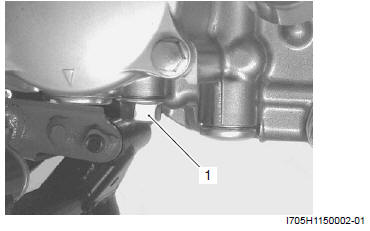
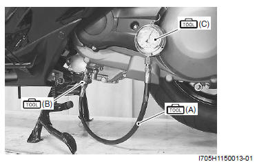
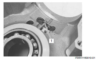
1) Remove the main oil gallery plug (1).
2) Install the oil pressure gauge and attachment to the main oil gallery.
Special tool
(A): 09915-74521 (Oil pressure gauge hose)
(B): 09915-74570 (Oil pressure gauge attachment)
(C): 09915-77331 (Meter (for high pressure) )
3) Warm up the engine as follows: Summer: 10 min at 2 000 r/min Winter: 20 min at 2 000 r/min 4) After warm up, increase the engine speed to 3 000 r/ min (Observe the tachometer), and read the oil pressure gauge.
If the oil pressure is lower or higher than the specification, the following causes may be considered.
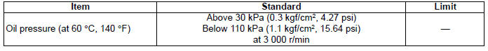
Oil pressure specification
Above 30 kPa (0.3 kgf/cm2, 4.27 psi) at 3 000 r/ min, oil temp. at 60 ºC (86
ºF)
Below 110 kPa (11.0 kgf/cm2, 15.64 psi) at 3 000 r/ min, oil temp. at 60 ºC (86
ºF)
High oil pressure
- Engine oil viscosity is too high
- Clogged oil passage
- Combination of the above items
Low oil pressure
- Clogged oil filter
- Oil leakage from the oil passage
- Damaged O-ring
- Defective oil pump
- Combination of the above items
5) Stop the engine and remove the oil pressure gauge and attachment.
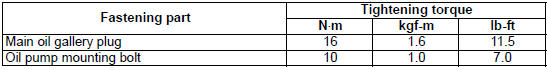
6) Reinstall the main oil gallery plug and tighten it to the specified torque.
! CAUTION Use a new gasket to prevent oil leakage.
Tightening torque
Main oil gallery plug: 16 N*m (1.6 kgf-m, 11.5 lb-ft)
7) Check the engine oil level. Refer to "Engine Oil and Filter Change".
Repair Instructions
Engine Oil and Filter Replacement
Refer to "Engine Oil and Filter Change".
Oil Sump Filter Removal and Installation
Removal
1) Dismount the engine. Refer to "Engine Assembly Removal and Installation".
2) Separate the crankcase. Refer to "Engine Bottom Side Disassembly".
3) Remove the oil sump filter from the left crankcase.
Refer to "Engine Bottom Side Disassembly".
Installation
Install the oil sump filter in the reverse order of removal.
Pay attention to the following points:
- Install the oil sump filter (1).
! CAUTION
- The lip "A" of the oil sump filter should be positioned downward.
- The shorter side "B" of the oil sump filter should be positioned inside.
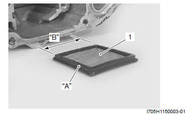
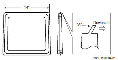
- Lip
- Shorter side
Oil Sump Filter Cleaning
Clean the oil sump filter in the following procedures:
1) Remove the oil sump filter. Refer to "Oil Sump Filter Removal and Installation".
2) Clean the oil sump filter using compressed air.
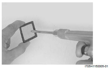
3) Install the oil sump filter. Refer to "Oil Sump Filter Removal and Installation"
Oil Pump Removal and Installation
Removal
1) Dismount the engine. Refer to "Engine Assembly Removal and Installation".
2) Separate the crankcase. Refer to "Engine Bottom Side Disassembly".
3) Remove the oil pump assembly from the left crankcase. Refer to "Engine Bottom Side Disassembly".
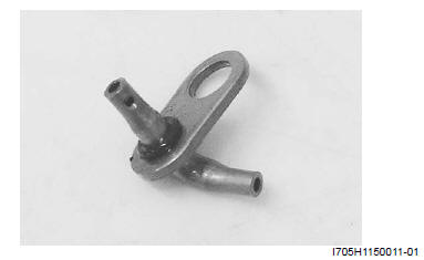
4) Remove the snap ring (1) and oil pump drain driven gear (2).
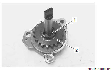
5) Remove the pin (3) and washer (4).
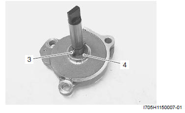
! CAUTION
- Do not attempt to disassemble the oil pump.
- The oil pump is available only as an assembly.
Installation
Install the oil pump in the reverse order of removal. Pay attention to the following point:
- Tighten the oil pump mounting bolts to the specified torque.
Tightening torque
Oil pump mounting bolt: 10 N*m (1.0 kgf-m, 7.0 lb-ft)
Oil Pump Inspection
Inspect the oil pump in the following procedures:
1) Remove the oil pump. Refer to "Oil Pump Removal and Installation ".
2) Rotate the oil pump shaft by hand and check that it moves smoothly. If it does not move smoothly, replace the oil pump with a new one.
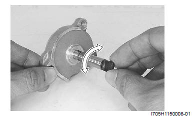
3) Install the oil pump in the reverse order of removal.
Refer to "Oil Pump Removal and Installation".
Piston Cooling Nozzle Removal and Installation
Removal
1) Dismount the engine. Refer to "Engine Assembly Removal and Installation".
2) Separate the crankcase. Refer to "Engine Bottom Side Disassembly".
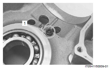
3) Remove the piston cooling nozzle (1) from the right crankcase.
Installation
Install the piston cooling nozzle in the reverse order of removal. Pay attention to the following point:
NOTE Before installing, replace the O-ring (1) with a new one and coat the O-ring with engine oil.
Piston Cooling Nozzle Inspection
Inspect the piston cooling nozzle in the following procedures:
1) Remove the piston cooling nozzle. Refer to "Piston Cooling Nozzle Removal and Installation ".
2) Inspect the piston cooling nozzle for clogging. If it is clogged, clean its oil passage with a proper wire or compressed air.
3) Install the piston cooling nozzle. Refer to "Piston Cooling Nozzle Removal and Installation".
Specifications
Service Data
Oil Pump
Tightening Torque Specifications
Reference: For the tightening torque of fastener not specified in this section, refer to "Tightening Torque Specifications".
Special Tools and Equipment
Special Tool
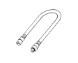 09915-74521
Oil pressure gauge hose
09915-74521
Oil pressure gauge hose
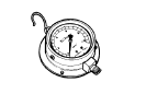 09915-77331
Meter (for high pressure)
09915-77331
Meter (for high pressure)
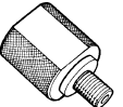 09915-74570
Oil pressure gauge attachment
09915-74570
Oil pressure gauge attachment
See also:
 Suzuki Burgman 400 - Service manual > Width Between Crankshaft Webs
Measure the width between crankshaft webs "a". Width between crankshaft webs "a" Standard: 59.9 - 60.1 mm (2.358 - 2.366 in)


