 Suzuki Burgman 400 - Service manual > Automatic Clutch
Automatic Clutch Inspection
This motorcycle is equipped with an automatic clutch and variable ratio belt drive transmission. The engagement of the clutch is governed by engine RPMs and centrifugal mechanism located in the clutch.
To insure proper performance and longer lifetime of the clutch assembly it is essential that the clutch engages smoothly and gradually. The following inspections must be performed.
Initial Engagement Inspection
1) Warm up the engine to normal operating temperature.
2) Remove the frame front cover. Refer to "Front Frame Cover Removal and Installation".
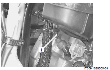
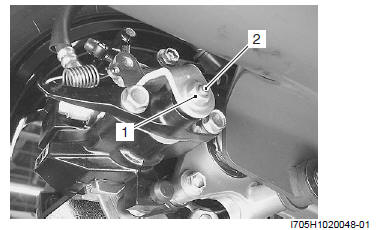
3) Connect the tachometer to the high-tension cord (1).
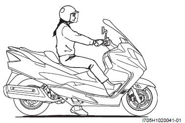
4) Seated on the motorcycle with the motorcycle on level ground, increase the engine RPMs slowly and note the RPM at which the motorcycle begins to move forward.
Special tool : 09900-26006 (Engine tachometer (solar cell type) )
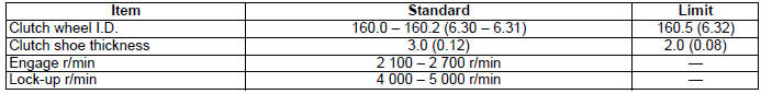
Engagement r/min
2 100 - 2 700 r/min
5) Disconnect the tachometer and install the frame front cover.
Clutch "Lock-up" Inspection
Perform this inspection to determine if the clutch is engaging fully and not slipping.
1) Warm up the engine to normal operating temperature.
2) Remove the frame front cover. Refer to "Front Frame Cover Removal and Installation".
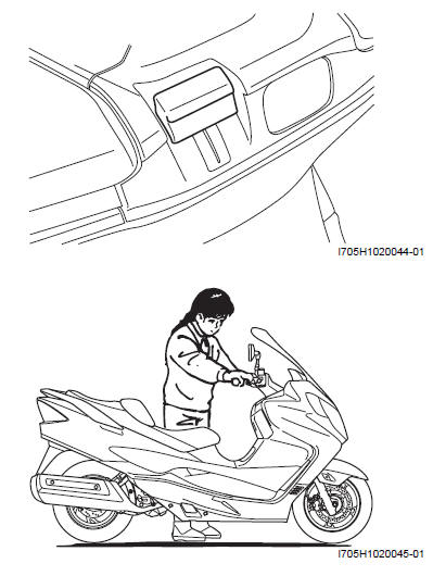
3) Apply the front and rear brakes as firm as possible.
4) Briefly open the throttle fully and note the maximum engine RPMs sustained during the test cycle.
! CAUTION Do not apply full power for more than 3 seconds or damage to the clutch or engine may occur.
Lock-up r/min
4 000 - 5 000 r/min
Parking Brake (Brake-lock) Inspection
Inspect that the wheel is locked up when pulling the brake-lock lever 2 - 4 notches and moving the motorcycle forward to make sure that the brake-lock acts enough.
Parking Brake (Brake-lock) Adjustment
Adjust the brake-lock in the following procedures:
1) Pull the brake-lock lever by one step (1 notch).
NOTE The brake-lock lever have 2 - 4 steps (2 - 4 notches) when pulling in fully.
2) With the lock-nut (1) loosening, adjust the adjuster bolt (2) in until the brake pad comes in contact with brake disc.
3) Tighten the lock-nut (1).
4) Return the brake-lock lever to original position and inspect the brake-lock.
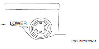
! CAUTION After the brake-lock adjustment, inspect the brake fluid level of rear brake.
Specifications
Tightening Torque Specifications
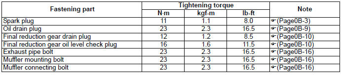
NOTE The specified tightening torque is also described in the following.
Reference: For the tightening torque of fastener not specified in this section, refer to "Tightening Torque Specifications".
Special Tools and Equipment
Recommended Service Material

NOTE Required service material is also described in the following.
Special Tool
 09900-20803 Thickness gauge
 09900-26006 Engine tachometer (solar
cell type)
09900-26006 Engine tachometer (solar
cell type)
 09900-20805 Tire depth gauge
 09930-10121 Spark plug wrench set
Service Data
Specifications
Service Data
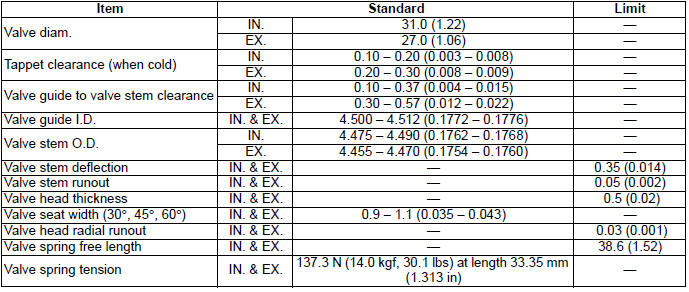
Valve + Valve Guide
Unit: mm (in)
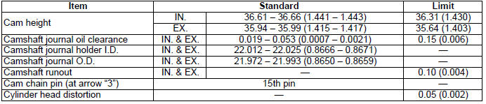
Camshaft + Cylinder Head
Unit: mm (in)
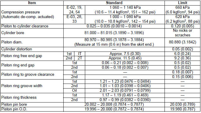
Cylinder + Piston + Piston Ring
Unit: mm (in)
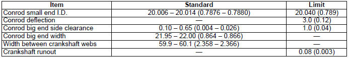
Conrod + Crankshaft
Unit: mm (in)
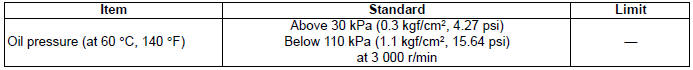
Oil Pump
Clutch
Unit: mm (in)
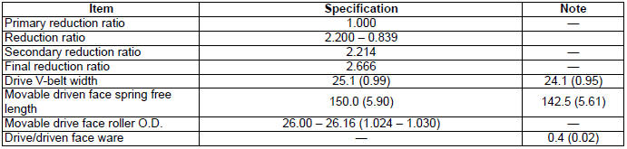
Transmission
Unit: mm (in) Except ratio
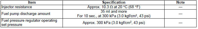
Injector + Fuel Pump + Fuel Pressure Regulator
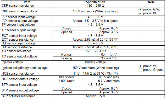
FI Sensors
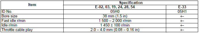
Throttle Body
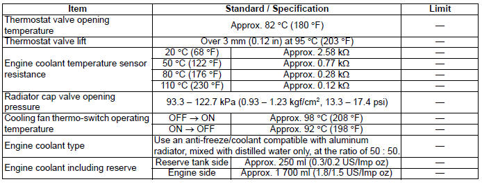
Thermostat + Radiator + Fan + Coolant
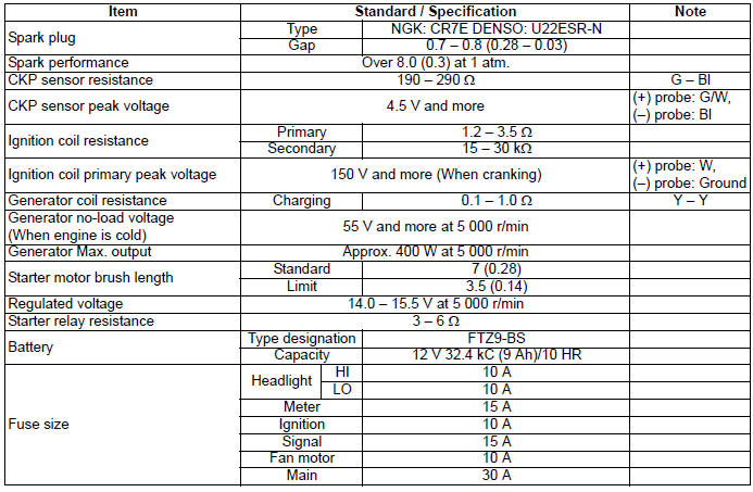
Electrical
Unit: mm (in)
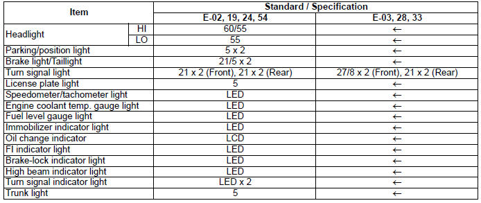
Wattage
Unit: W
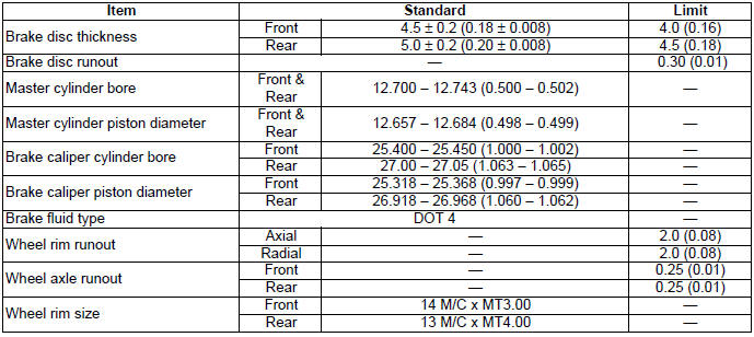
Brake + Wheel
Unit: mm (in)
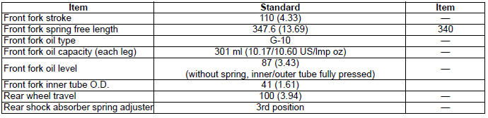
Suspension
Unit: mm (in)
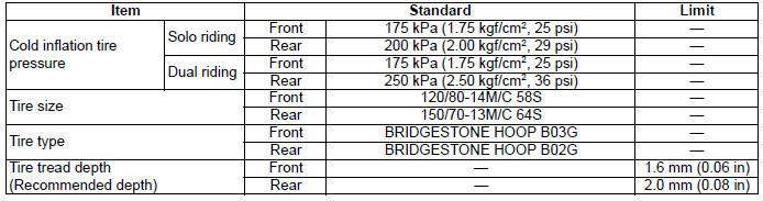
Tire
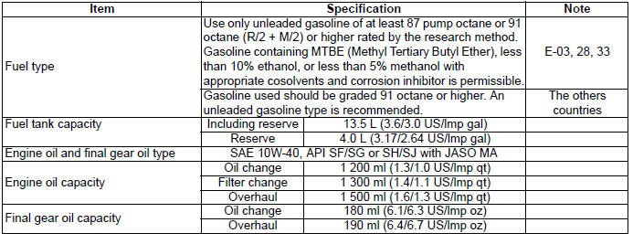
Fuel + Oil
Tightening Torque Specifications
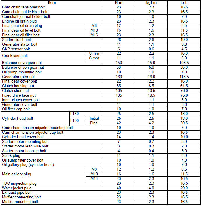
Engine
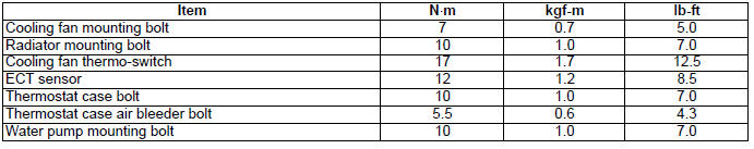
Cooling System
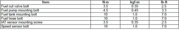
FI System and Intake Air System
Chassis
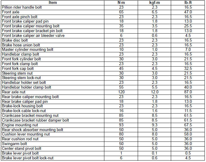
Tightening Torque Chart
For other bolts and nuts not listed in the preceding page, refer to this chart:
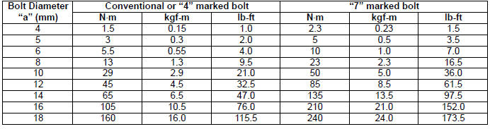
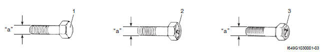
- Conventional bolt
- "4" marked bolt
- "7" marked bolt
See also:
 Suzuki Burgman 400 - Service manual > Chassis Bolt and Nut
Chassis Bolt and Nut Inspection Tighten chassis bolt and nut Initially at 1 000 km (600 miles, 2 month) and every 6 000 km (4 000 miles, 12 months) thereafter


