 Suzuki Burgman 400 - Service manual > Body Structure
Repair Instructions
Body Frame Construction
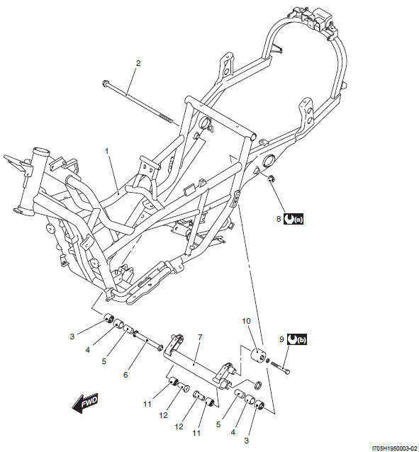
- Frame
- Crankcase bracket bolt
- Bushing
- Bearing
- Spacer
- Collar
- Crankcase bracket
- Crankcase bracket nut
- Rubber damper bolt
- Rubber damper
- Bearing
- Collar
- : 102 N*m (10.2 kgf-m, 73.5 lb-ft)
- : 102 N*m (10.2 kgf-m, 73.5 lb-ft)
Engine Mounting Bracket Bushing Replacement
Replace the engine mounting bracket bushing if necessary. Refer to "Body Frame Construction".
Engine Mounting Bushing Replacement
Replace the engine mounting bushing if necessary. Refer to "Body Frame Construction".
Side-stand Construction
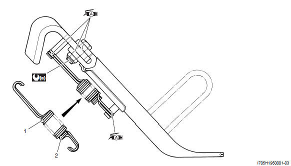
- Outer spring
- Inner spring
- : 50N*m (5.0 kgf-m, 36.0 lb-ft)
 : Apply grease.
Side-stand Removal and Installation
Removal
1) Support the motorcycle with the center stand.
2) Remove the side-stand. Refer to "Side-stand Construction".
Installation
Install the side-stand. Refer to "Side-stand Construction".
Center Stand Construction
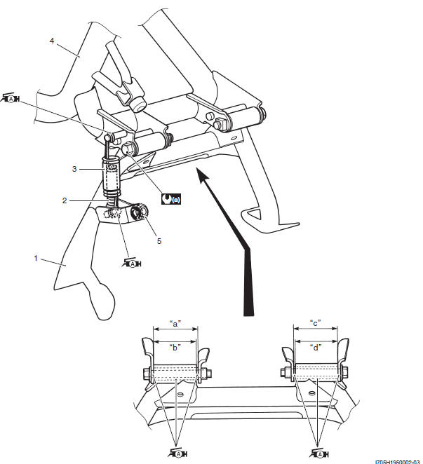
- Center stand
- Center stand inner spring
- Center stand outer spring
- Frame
- Cushion
- 60 mm (2.36 in)
- 57 mm (2.24 in)
- 60 mm (2.36 in)
- 57 mm (2.24 in)
 a : 50 N*m (5.0 kgf-m,
36.0 lb-ft)
 : Apply grease to
sliding surface.
Center Stand Removal and Installation
Removal
1) Support the motorcycle using a jack.
! CAUTION Make sure that the motorcycle is supported securely.
2) Remove the center stand. Refer to "Center Stand Construction".
Installation
Install the center stand. Refer to "Center Stand Construction".
Specifications
Tightening Torque Specifications
NOTE The specified tightening torque is also described in the following.
Reference: For the tightening torque of fastener not specified in this section, refer to "Tightening Torque Specifications".
Special Tools and Equipment
Recommended Service Material
NOTE Required service material is also described in the following.
See also:
 Suzuki Burgman 400 - Service manual > Lower Frame Cover Removal and Installation
Removal Pull out the lower frame cover (1). Installation Push in the lower frame cover (1). Hooked point


