 Yamaha XMAX YP125R - Service manual > Charging method using a constant voltage charger
a. Measure the open-circuit voltage prior to charging.
TIP
Voltage should be measured 30 minutes after the engine is turned off.
b. Connect a charger and ammeter to the battery and start charging.
c. Make sure that the current is higher than the standard charging current written on the battery.
TIP
If the current is lower than the standard charging current written on the battery, this type of battery charger cannot charge the VRLA (Valve Regulated Lead Acid) battery. A variable voltage charger is recommended.
d. Charge the battery until the battery's charging voltage is 15 V.
TIP
Set the charging time at 20 hours (maximum).
e. Measure the battery open-circuit voltage after leaving the battery unused for more than 30 minutes.
12.8 V or more --- Charging is complete.
12.7 V or less --- Recharging is required.
Under 12.0 V --- Replace the battery.
6. Install:
- Battery
7. Connect:
- Battery leads (to the battery terminals)
NOTICE
First, connect the positive battery lead "1", and then the negative battery lead "2".
8. Check:
- Battery terminals
Dirt → Clean with a wire brush.
Loose connection → Connect properly.
9. Install:
- Upper panel
Checking the relays
Check each switch for continuity with the pocket tester. If the continuity reading is incorrect, replace the relay.
 Pocket tester 90890-03112
Analog pocket tester YU-03112-C
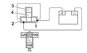
1. Disconnect the relay from the wire harness.
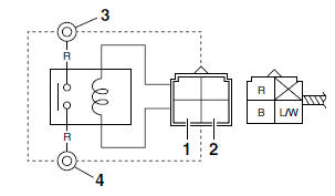
2. Connect the pocket tester (Ω × 1) and battery (12 V) to the relay terminal as shown.
Check the relay operation.
Out of specification → Replace.
Starting circuit cut-off relay
- Positive battery terminal
- Negative battery terminal
- Positive tester probe
- Negative tester probe
 Result Continuity (between "3" and "4")
Starter relay
- Positive battery terminal
- Negative battery terminal
- Positive tester probe
- Negative tester probe
 Result Continuity (between "3" and "4")
Headlight relay
- Positive battery terminal
- Negative battery terminal
- Positive tester probe
- Negative tester probe
 Result Continuity (between "3" and "4")
Radiator fan motor relay
- Positive battery terminal
- Negative battery terminal
- Positive tester probe
- Negative tester probe
 Result Continuity (between "3" and "4")
Checking the turn signal/hazard relay
1. Check:
- Turn signal/hazard relay input voltage Out of specification → The wiring circuit from the main switch to the turn signal/hazard relay coupler is faulty and must be repaired.
 Turn signal/hazard relay input voltage DC 12 V
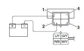
a. Connect the pocket tester (DC 20 V) to the turn signal/hazard relay terminal as shown.
 Pocket tester 90890-03112
Analog pocket tester YU-03112-C
- Positive tester probe → brown/red "1"
- Negative tester probe → ground
b. Set the main switch to "ON".
c. Measure the turn signal/hazard relay input voltage.
2. Check:
- Turn signal/hazard relay output voltage Out of specification → Replace.
 Turn signal/hazard relay output voltage DC 12 V
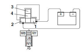
a. Connect the pocket tester (DC 20 V) to the turn signal/hazard relay terminal as shown.
 Pocket tester 90890-03112
Analog pocket tester YU-03112-C
- Positive tester probe → brown/white "1"
- Negative tester probe → ground
b. Set the main switch to "ON".
c. Measure the turn signal/hazard relay output voltage.
See also:
 Yamaha XMAX YP125R - Service manual > Checking the condition of the bulb sockets
The following procedure applies to all of the bulb sockets. 1. Check: Bulb socket (for continuity) (with the pocket tester) No continuity → Replace. Pocket tester 90890-03112
Yamaha XMAX YP125R - Service manual > Checking the spark plug cap
1. Check: Spark plug cap resistance Out of specification → Replace. Resistance 10.0 kΩ


