 Yamaha XMAX YP125R - Service manual > Checking the coolant temperature sensor
1. Remove:
- Coolant temperature sensor Refer to "CYLINDER HEAD (YP125R)" and "CYLINDER HEAD (YP250R)"
WARNING
- Handle the coolant temperature sensor with special care.
- Never subject the coolant temperature sensor to strong shocks. If the coolant temperature sensor is dropped, replace it.
2. Check:
Coolant temperature sensor resistance Out of specification → Replace.
 Coolant temperature sensor resistance 2.32-2.59 kΩ at 20 ºC (68 ºF) 310-326 Ω at 80 ºC (176 ºF)
a. Connect the pocket tester (Ω × 1k/× 100) to the coolant temperature sensor terminals as shown.
 Pocket tester 90890-03112
Analog pocket tester YU-03112-C
b. Immerse the coolant temperature sensor "1" in a container filled with coolant "2".
TIP
Make sure the coolant temperature sensor terminals do not get wet.
c. Place a thermometer "3" in the coolant.
d. Heat the coolant or let it cool down to the specified temperatures.
e. Measure the coolant temperature sensor resistances.
3. Install:
- Coolant temperature sensor
 Coolant temperature sensor 18 Nm (1.8 m*kgf, 13 ft*lbf)
Checking the throttle position sensor
1. Check:
- Throttle position sensor
a. Connect the digital circuit tester to the throttle position sensor as shown.
 Digital circuit tester 90890-03174
Model 88 Multimeter with tachometer YU-A1927
- Positive tester probe → gray/red "1"
- Negative tester probe → gray/black "2"
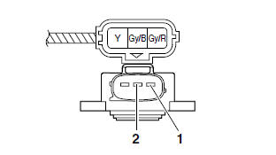
b. Measure the throttle position sensor voltage.
Out of specification → Replace or repair the wire harness.
 Throttle position sensor voltage 5 V (gray/red-gray/black)
c. Connect the digital circuit tester to the throttle position sensor as shown.
- Positive tester probe → yellow "1"
- Negative tester probe → gray/black "2"
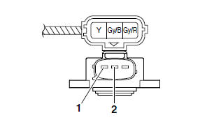
d. While slowly opening the throttle, check that the throttle position sensor voltage is increased.
Voltage does not change or it changes abruptly → Replace the throttle position sensor.
Out of specification (closed position) → Replace the throttle position sensor.
 Throttle position sensor voltage (closed position) 0.40-0.90 V (yellow-gray/black)
Checking the intake air pressure sensor
1. Check:
- Intake air pressure sensor output voltage Out of specification → Replace.
 Intake air pressure sensor output voltage 3.57-3.71 V
a. Connect the test harness between the intake air pressure sensor and wire harness.
b. Connect the pocket tester (DC 20 V) to the test harness.
 Test harness 90890-03204
Pocket tester 90890-03112
Analog pocket tester YU-03112-C
- Positive tester probe → pink/white "1"
- Negative tester probe → gray/black "2"
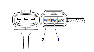
c. Set the main switch to "ON".
d. Measure the intake air pressure sensor output voltage.
Checking the intake air temperature sensor
1. Remove:
- Intake air temperature sensor (from the air filter case)
WARNING
- Handle the intake air temperature sensor with special care.
- Never subject the intake air temperature sensor to strong shocks. If the intake air temperature sensor is dropped, replace it.
2. Check:
- Intake air temperature sensor resistance Out of specification → Replace.
 Intake air temperature sensor resistance 2.21-2.69 kΩ at 20 ºC (68 ºF)
a. Connect the pocket tester (Ω × 1k) to the intake air temperature sensor terminal as shown.
 Pocket tester 90890-03112
Analog pocket tester YU-03112-C
b. Immerse the intake air temperature sensor "1" in a container filled with water "2".
TIP
Make sure that the intake air temperature sensor terminals do not get wet.
c. Place a thermometer "3" in the water.
d. Heat the water or let it cool down to the specified temperature.
e. Measure the intake air temperature sensor resistance.
Checking the air temperature sensor
1. Remove:
- Air temperature sensor
WARNING
- Handle the air temperature sensor with special care.
- Never subject the air temperature sensor to strong shocks. If the air temperature sensor is dropped, replace it.
2. Check:
- Air temperature sensor resistance Out of specification → Replace.
 Air temperature sensor resistance 4.19-4.63 kΩ at 50 ºC (122 ºF)
a. Connect the pocket tester (Ω × 1k) to the air temperature sensor terminal as shown.
 Pocket tester 90890-03112
Analog pocket tester YU-03112-C
b. Immerse the air temperature sensor "1" in a container filled with water "2".
TIP
Make sure that the air temperature sensor terminals do not get wet.
c. Place a thermometer "3" in the water.
d. Heat the water or let it cool down to the specified temperatures.
e. Measure the air temperature sensor resistance.
Checking the isc (idle speed control) unit
TIP
Do not remove the ISC unit completely from the throttle body.
1. Check:
- ISC unit
a. Disconnect the ISC unit coupler from the ISC unit.
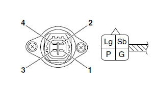
b. Connect the pocket tester (Ω × 10) to the terminals of the ISC unit.
 Pocket tester 90890-03112
Analog pocket tester YU-03112-C
- Positive tester probe → pink "1"
- Negative tester probe → light green "2"
- Positive tester probe → green "3"
- Negative tester probe → sky blue "4"
c. Measure the ISC unit resistance.
Out of specification → Replace the throttle body.
 ISC unit resistance 27-33 Ω at 20 ºC (68 ºF)
Checking the v-belt replacement indicator reset Coupler
1. Remove:
- V-belt replacement indicator reset coupler
2. Check:
- V-belt replacement indicator reset coupler Out of specification → Replace the V-belt replacement indicator coupler.
 Continuity Positive tester probe → black "1"
Negative tester probe → black "2"
Continuity Positive tester probe → black "2"
Negative tester probe → black "1"
a. Connect the pocket tester (Ω × 1) to the Vbelt replacement indicator reset coupler terminals.
 Pocket tester 90890-03112
Analog pocket tester YU-03112-C
b. Check the V-belt replacement indicator reset coupler for continuity.
See also:
 Yamaha XMAX YP125R - Service manual > Checking the lean angle sensor
1. Remove: Lean angle sensor 2. Check: Lean angle sensor output voltage Out of specification → Replace. Lean angle sensor output voltage
Yamaha XMAX YP125R - Service manual > Troubleshooting
General information TIP The following guide for troubleshooting does not cover all the possible causes of trouble. It should be helpful, however, as a guide to basic troubleshooting.


