 Yamaha XMAX YP125R - Service manual > Troubleshooting
General information
TIP
The following guide for troubleshooting does not cover all the possible causes of trouble. It should be helpful, however, as a guide to basic troubleshooting.
Refer to the relative procedure in this manual for checks, adjustments, and replacement of parts.
Starting failure/hard starting
Engine
1. Cylinder and cylinder head
- Loose spark plug
- Loose cylinder head or cylinder
- Damaged cylinder head gasket
- Damaged cylinder gasket
- Worn or damaged cylinder
- Incorrect valve clearance
- Improperly sealed valve
- Incorrect valve-to-valve-seat contact
- Incorrect valve timing
- Faulty valve spring
- Seized valve
2. Piston and piston ring(s)
- Improperly installed piston ring
- Damaged, worn or fatigued piston ring
- Seized piston ring
- Seized or damaged piston
3. Air filter
- Improperly installed air filter
- Clogged air filter element
4. Crankcase and crankshaft
- Improperly assembled crankcase
- Seized crankshaft
Fuel system
1. Fuel tank
- Empty fuel tank
- Clogged fuel tank cap breather hole
- Deteriorated or contaminated fuel
- Clogged or damaged fuel hose
2. Fuel pump
- Faulty fuel pump
- Clogged fuel pump filter
3. Throttle body
- Deteriorated or contaminated fuel
- Sucked-in air
Electrical system
1. Battery
- Discharged battery
- Faulty battery
2. Fuse(s)
- Blown, damaged or incorrect fuse
- Improperly installed fuse
3. Spark plug
- Incorrect spark plug gap
- Incorrect spark plug heat range
- Fouled spark plug
- Worn or damaged electrode
- Worn or damaged insulator
- Faulty spark plug cap
4. Ignition coil
- Cracked or broken ignition coil body
- Broken or shorted primary or secondary coils
- Faulty spark plug lead
5. Ignition system
- Faulty ECU
- Faulty crankshaft position sensor
- Broken generator rotor woodruff key
6. Switches and wiring
- Faulty main switch
- Broken or shorted wiring
- Faulty front, rear or both brake light switches
- Faulty start switch
- Faulty sidestand switch
- Improperly grounded circuit
- Loose connections
7. Starting system
- Faulty starter motor
- Faulty starter relay
- Faulty starting circuit cut-off relay
- Faulty starter clutch
Incorrect engine idling speed
Engine
1. Cylinder and cylinder head
- Incorrect valve clearance
- Damaged valve train components
2. Air filter
- Clogged air filter element
Fuel system
1. Throttle body
- Damaged or loose throttle body joint
- Improper throttle cable free play
Electrical system
1. Battery
- Discharged battery
- Faulty battery
2. Spark plug
- Incorrect spark plug gap
- Incorrect spark plug heat range
- Fouled spark plug
- Worn or damaged electrode
- Worn or damaged insulator
- Faulty spark plug cap
3. Ignition coil
- Faulty spark plug lead
4. Ignition system
- Faulty ECU
- Faulty crankshaft position sensor
Poor medium-and-high-speed performance
Engine
1. Air filter
- Clogged air filter element
Fuel system
1. Fuel pump
- Faulty fuel pump
Faulty clutch
Engine operates but vehicle will not move
1. V-belt
- Bent, damaged or worn V-belt
- Slipping V-belt
2. Primary pulley cam and primary pulley slider( s)
- Damaged or worn primary pulley cam
- Damaged or worn primary pulley slider
3. Transmission gear(s)
- Damaged transmission gear
Clutch slips
1. Clutch shoe spring(s)
- Damaged, loose or worn clutch shoe spring
2. Clutch shoe(s)
- Damaged or worn clutch shoe
3. Primary sliding sheave
- Seized primary sliding sheave
Poor starting performance
1. V-belt
- V-belt slips
- Oil or grease on the V-belt
2. Primary sliding sheave
- Faulty operation
3. Clutch shoe(s)
- Bent, damaged or worn clutch shoe
Poor speed performance
1. V-belt
- Oil or grease on the V-belt
2. Primary pulley weight(s)
- Faulty operation
- Worn primary pulley weight
3. Primary fixed sheave
- Worn primary fixed sheave
4. Primary sliding sheave
- Worn primary sliding sheave
5. Secondary fixed sheave
- Worn secondary fixed sheave
6. Secondary sliding sheave
- Worn secondary sliding sheave
Overheating
Engine
1. Clogged coolant passages
- Cylinder head and piston
- Heavy carbon buildup
2. Engine oil
- Incorrect oil level
- Incorrect oil viscosity
- Inferior oil quality
Cooling system
1. Coolant
- Low coolant level
2. Radiator
- Damaged or leaking radiator
- Faulty radiator cap
- Bent or damaged radiator fin
3. Water pump
- Damaged or faulty water pump
4. Thermostat
- Thermostat stays closed
5. Hose(s)
- Damaged hose
- Improperly connected hose
Fuel system
1. Throttle body
- Damaged or loose throttle body joint
2. Air filter
- Clogged air filter element
Chassis
1. Brake(s)
- Dragging brake
Electrical system
1. Spark plug
- Incorrect spark plug gap
- Incorrect spark plug heat range
2. Ignition system
- Faulty ECU
Overcooling
Cooling system
1. Thermostat
- Thermostat stays open
Poor braking performance
- Worn brake pad
- Worn brake disc
- Air in hydraulic brake system
- Leaking brake fluid
- Faulty brake caliper kit
- Faulty brake caliper seal
- Loose union bolt
- Damaged brake hose
- Oil or grease on the brake disc
- Oil or grease on the brake pad
- Incorrect brake fluid level
Faulty front fork legs
Leaking oil
- Bent, damaged or rusty inner tube
- Cracked or damaged outer tube
- Improperly installed oil seal
- Damaged oil seal lip
- Incorrect oil level (high)
- Loose damper rod bolt
- Damaged damper rod bolt copper washer
- Cracked or damaged front fork cap O-ring
Malfunction
- Bent or damaged inner tube
- Bent or damaged outer tube
- Damaged fork spring
- Worn or damaged outer tube bushing
- Bent or damaged damper rod
- Incorrect oil viscosity
- Incorrect oil level
Unstable handling
1. Handlebar
- Bent or improperly installed handlebar
2. Steering head components
- Improperly installed lower handlebar holder
- Improperly installed lower bracket (improperly tightened ring nut)
- Bent steering stem
- Damaged ball bearing or bearing race
3. Front fork leg(s)
- Uneven oil levels (both front fork legs)
- Unevenly tensioned fork spring (both front fork legs)
- Broken fork spring
- Bent or damaged inner tube
- Bent or damaged outer tube
4. Swingarm
- Worn bearing or bushing
- Bent or damaged swingarm
5. Rear shock absorber assembly(-ies)
- Faulty rear shock absorber spring
- Leaking oil
6. Tire(s)
- Uneven tire pressures (front and rear)
- Incorrect tire pressure
- Uneven tire wear
7. Wheel(s)
- Incorrect wheel balance
- Deformed cast wheel
- Damaged wheel bearing
- Bent or loose wheel axle
- Excessive wheel runout
8. Frame
- Bent frame
- Damaged steering head pipe
- Improperly installed bearing race
Faulty lighting or signaling system
Headlight does not come on
- Wrong headlight bulb
- Too many electrical accessories
- Hard charging
- Incorrect connection
- Improperly grounded circuit
- Poor contacts (main switch)
- Burnt-out headlight bulb
Headlight bulb burnt out
- Wrong headlight bulb
- Faulty battery
- Faulty rectifier/regulator
- Improperly grounded circuit
- Faulty main switch
- Headlight bulb life expired
Tail/brake light does not come on
- Wrong tail/brake light bulb
- Too many electrical accessories
- Incorrect connection
- Burnt-out tail/brake light bulb
Tail/brake light bulb burnt out
- Wrong tail/brake light bulb
- Faulty battery
- Tail/brake light bulb life expired
Turn signal does not come on
- Faulty turn signal switch
- Faulty turn signal/hazard relay
- Burnt-out turn signal bulb
- Incorrect connection
- Damaged or faulty wire harness
- Improperly grounded circuit
- Faulty battery
- Blown, damaged or incorrect fuse
Turn signals flash slowly
- Faulty turn signal/hazard relay
- Faulty main switch
- Faulty turn signal switch
- Incorrect turn signal bulb
Turn signals remain lit
- Faulty turn signal/hazard relay
- Burnt-out turn signal bulb
Turn signals flash quickly
- Incorrect turn signal bulb
- Faulty turn signal/hazard relay
- Burnt-out turn signal bulb
Horn does not sound
- Damaged or faulty horn
- Faulty main switch
- Faulty horn switch
- Faulty battery
- Blown, damaged or incorrect fuse
- Faulty wire harness
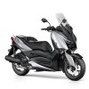
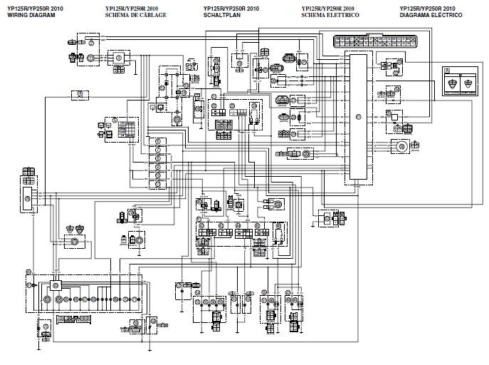
Wiring diagram
YP125R/YP250R 2010
1. AC magneto
2. Crankshaft position sensor
3. Rectifier/regulator
4. Backup fuse (immobilizer unit and meter assembly)
5. Main switch
6. ECU fuse
7. Radiator fan motor fuse
8. Turn signal/hazard fuse
9. Ignition fuse
10.Headlight fuse
11. Signaling system fuse
12. Battery
13. Main fuse
14. Starter relay
15. Starter motor
16. Diode
17.Frame ground
18. Sidestand switch
19.Fuel pump
20. Starting circuit cut-off relay
21. Right handlebar switch
22. Start switch
23.Hazard switch
24. Front brake light switch
25.Coolant temperature sensor
26. Throttle position sensor
27. Intake air pressure sensor
28. Intake air temperature sensor
29.Lean angle sensor
30.Speed sensor
31.ECU (engine control unit)
32. Ignition coil
33.Spark plug
34.Fuel injector
35.O2 sensor
36. ISC (idle speed control) unit
37. Auxiliary DC jack (OPTION)
38.Horn
39. Turn signal/hazard relay
40.Headlight relay
41.Left handlebar switch
42. Dimmer switch
43.Pass switch
44. Turn signal switch
45.Horn switch
46. Rear brake light switch
47. Right tail/brake light assembly
48. Right rear turn signal light
49. Tail/brake light
50.Left tail/brake light assembly
51.Left rear turn signal light
52. Right front turn signal light
53.Left front turn signal light
54.Headlight assembly
55.Headlight
56.Auxiliary light
57.License plate light
58.Fuel sender
59.V-belt replacement indicator reset coupler
60.Meter assembly
61. Immobilizer system indicator light
62.Multifunction meter
63.Speedometer
64.Tachometer
65.Engine oil change indicator
66.V-belt replacement indicator
67.Engine trouble warning light
68.Meter light
69.High beam indicator light
70.Right turn signal indicator light
71. Left turn signal indicator light
72.Air temperature sensor
73.Radiator fan motor
74.Radiator fan motor relay
75.Self-diagnosis signal coupler
76. Immobilizer unit
A. YP250R only
COLOR CODE
B- Black
Br- Brown
Ch- Chocolate
Dg- Dark green
G- Green
Gy- Gray
L- Blue
Lg- Light green
O- Orange
P- Pink
R- Red
Sb- Sky blue
W- White
Y- Yellow
B/L- Black/Blue
B/R- Black/Red
B/W- Black/White
Br/L- Brown/Blue
Br/R- Brown/Red
Br/W- Brown/White
G/B- Green/Black
G/L- Green/Blue
G/R- Green/Red
G/Y- Green/Yellow
Gy/B- Gray/Black
Gy/G- Gray/Green
Gy/R- Gray/Red
L/B- Blue/Black
L/R- Blue/Red
L/W- Blue/White
L/Y- Blue/Yellow
O/B- Orange/Black
O/R- Orange/Red
P/W- Pink/White
R/B- Red/Black
R/G- Red/Green
R/L- Red/Blue
R/W- Red/White
R/Y- Red/Yellow
W/B- White/Black
W/R- White/Red
W/Y- White/Yellow
Y/G- Yellow/Green
Y/L- Yellow/Blue
See also:
 Yamaha XMAX YP125R - Service manual > Checking the coolant temperature sensor
1. Remove: Coolant temperature sensor Refer to "CYLINDER HEAD (YP125R)" and "CYLINDER HEAD (YP250R)" WARNING Handle the coolant temperature sensor with special care. Never subject the coolant temperature sensor to strong shocks. If the coolant temperature sensor is dropped, replace it.


