 Yamaha XMAX YP125R - Service manual > Checking the switches
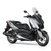
- Start switch
- Hazard switch
- Front brake light switch
- Main switch
- Dimmer switch
- Pass switch
- Turn signal switch
- Horn switch
- Rear brake light switch
- Sidestand switch
Check each switch for continuity with the pocket tester. If the continuity reading is incorrect, check the wiring connections and, if necessary, replace the switch.
NOTICE
Never insert the tester probes into the coupler terminal slots "a". Always insert the probes from the opposite end of the coupler, taking care not to loosen or damage the leads.
 Pocket tester 90890-03112
Analog pocket tester YU-03112-C
TIP
- Before checking for continuity, set the pocket tester to "0" and to the "Ω × 1" range.
- When checking for continuity, switch back and forth between the switch positions a few times.
The switches and their terminal connections are illustrated as in the following example of the main switch.
The switch positions "a" are shown in the far left column and the switch lead colors "b" are shown in the top row.
The continuity (i.e., a closed circuit) between switch terminals at a given switch position is indicated by "  ". There is continuity between red, brown/blue, and brown/red when the switch is set to "ON".
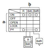
Checking the bulbs and bulb sockets
TIP
Do not check any of the lights that use LEDs.
Check each bulb and bulb socket for damage or wear, proper connections, and also for continuity between the terminals.
Damage/wear → Repair or replace the bulb, bulb socket or both.
Improperly connected → Properly connect.
No continuity → Repair or replace the bulb, bulb socket or both.
Types of bulbs
The bulbs used on this vehicle are shown in the illustration.
- Bulbs "a" and "b" are used for the headlights and usually use a bulb holder that must be detached before removing the bulb. The majority of these types of bulbs can be removed from their respective socket by turning them counterclockwise.
- Bulbs "c" are used for turn signal and tail/brake lights and can be removed from the socket by pushing and turning the bulb counterclockwise.
Checking the condition of the bulbs
The following procedure applies to all of the bulbs.
1. Remove:
- Bulb
WARNING
Since headlight bulbs get extremely hot, keep flammable products and your hands away from them until they have cooled down.
NOTICE
- Be sure to hold the socket firmly when removing the bulb. Never pull the lead, otherwise it may be pulled out of the terminal in the coupler.
- Avoid touching the glass part of a headlight bulb to keep it free from oil, otherwise the transparency of the glass, the life of the bulb, and the luminous flux will be adversely affected. If the headlight bulb gets soiled, thoroughly clean it with a cloth moistened with alcohol or lacquer thinner.
2. Check:
- Bulb (for continuity) (with the pocket tester) No continuity → Replace.
 Pocket tester 90890-03112
Analog pocket tester YU-03112-C
TIP
Before checking for continuity, set the pocket tester to "0" and to the "Ω × 1" range.
a. Connect the positive tester probe to terminal "1" and the negative tester probe to terminal "2", and check the continuity.
b. Connect the positive tester probe to terminal "1" and the negative tester probe to terminal "3", and check the continuity.
c. If either of the readings indicate no continuity, replace the bulb.
See also:
 Yamaha XMAX YP125R - Service manual > Checking the condition of the bulb sockets
The following procedure applies to all of the bulb sockets. 1. Check: Bulb socket (for continuity) (with the pocket tester) No continuity → Replace. Pocket tester 90890-03112


