 PIAGGIO Beverly 300ie - Service manual > Circuit leak test
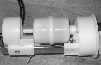
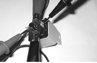
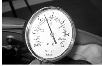
Install the specific tool for checking the fuel pressure, with the pipe fitted with the gauge.
Check during regular operation by placing the appropriate tool between the pump and the injector.
With the battery voltage > 12 V check that the fuel pressure is 2.5 BAR and that the input current is 1.4 to 1.8 A
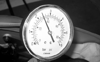
With the battery voltage > 12 V, check the capacity of the pump flow rate by disconnecting from the injector the pipe equipped with the pressure gauge of the appropriate tool. Make a graded burette available with a flowrate of approximately 1 L. Rotate the pump using the active diagnosis of the palm top computer. Using a pair of long flat needle-nose pliers, choke the fuel pipe making the pressure stabilise at approx. 2.5 BAR. Check that, in fifteen seconds, the pump has a flowrate of around 110cc.
Specific tooling
020480Y Petrol pressure check kit
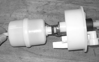
Fuel filter check
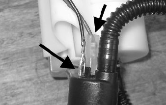
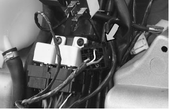
Disconnect the terminals from the electric pump
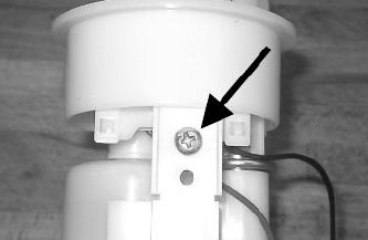
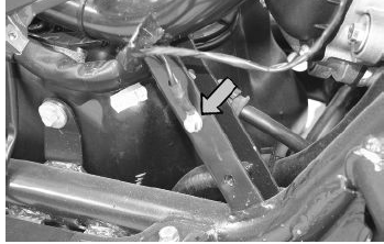
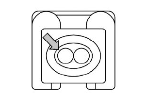
Remove the screw shown in the picture
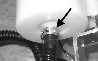
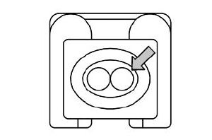
Remove the clip fixing the piping to the filter shown in the picture
Separate the lower part of the pump mounting as shown in the picture.
Remove the filter from the pump mounting
Inspecting the injector circuit
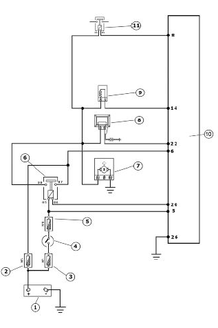
INJECTION LOADS
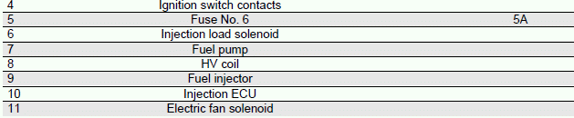
Check the resistance at the injector ends: 14.5 +- 5% Ohm
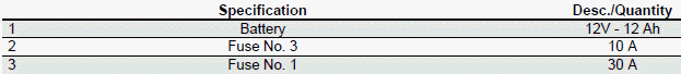
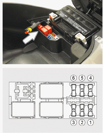
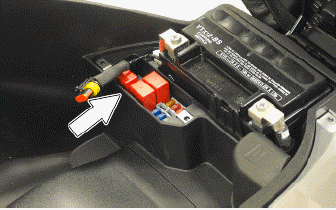
Check function of fuses No. 3 and 6 for the ECU and injection load solenoid.
Check the efficiency of the injection load solenoid.
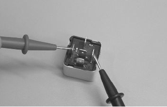
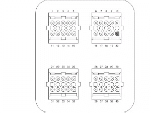
Check the resistance of the energising coil between pins 86 and 85: 40 to 80 Ohm
Apply a voltage of 12V to pins 86 and 85; make sure that there is continuity between pins 30 and 87 of the relay.
WARNING
TO INDICATE THE RELAY OF THE DESIRED FUNCTION, REFER TO THE PIN-CABLE COLOUR RELATIONSHIP WITH THE ATTACHED ELECTRIC SYSTEM DIAGRAM.
Check the power supply line of the injection load solenoid energising coil: after switching to "ON", make sure there is battery voltage, for 2 seconds, between the Red-White cable and the Black-Purple cable of the solenoid base. If there is not, check the continuity of the Red-White cable between the fuse box and the solenoid base and of the Black- Purple cable between the pin 20 of the control unit and the solenoid base.

N.B.
CONTINUITY TESTS MUST BE CARRIED OUT WITH THE COMPONENTS DISCONNECTED. (RELAYS, CONTROL UNIT, FUSES ETC.).
Check for continuous voltage between the grey/ black cable of the solenoid base and ground. If no voltage is measured, check continuity of the Grey/ Black cable between the fuse box (No. 3, 5A) and the solenoid base.
N.B.
CONTINUITY TESTS MUST BE CARRIED OUT WITH THE COMPONENTS DISCONNECTED. (RELAYS, CONTROL UNIT, FUSES ETC.).
With the control unit and the injector disconnected, check the continuity of the Red-Yellow cable between pin 14 of the interface wiring and the injector connector
Switch to "ON" and check if there is voltage, with injector disconnected and control unit connected, between the Black-Green cable of the injector connector and the ground lead
With injector disconnected and the injector load solenoid disconnected, check the continuity of the Black-Green cable between the injector connector and solenoid base.
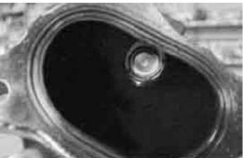
Inspecting the injector hydraulics
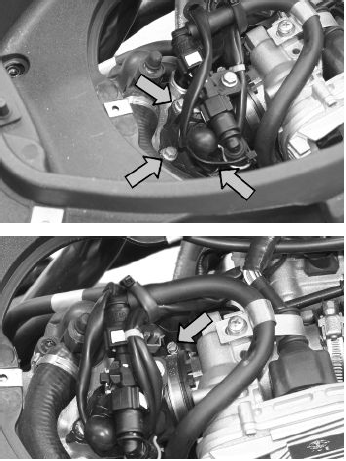
To carry out the injector check, remove the intake manifold by removing the three clamping screws at the head and the clip connecting the control unit to the manifold.
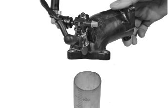
Install the appropriate tool for checking fuel pressure and position the manifold over a container graduated by at least 100 cm³. Connect the injector with the cable making up part of the supply for the injection tester. Connect the clamps of the cable to an auxiliary battery. Activate the fuel pump with the active diagnosis. Check that, within fifteen seconds, approximately 40 cm³ of fuel is dispensed with an adjustment pressure of approximately 2.5 BAR.
Specific tooling
020480Y Petrol pressure check kit
Proceed with the injector seal test.
Dry the injector outlet with a blast of compressed air. Activate the fuel pump. Wait for one minute, making sure there are no leaks coming from the injector. Slight oozing is normal.
Value limit = 1 drop per minute
See also:
 PIAGGIO Beverly 300ie - Service manual > Removing the butterfly valve
The fuel supply circuit includes the electric pump, the filter, the pressure regulator, the electro-injector and the fuel delivery pipes. The electrical pump is located in the tank from which the fuel is pumped and sent to the injector through the filter.


