 PIAGGIO Beverly 300ie - Service manual > Removing the butterfly valve
The fuel supply circuit includes the electric pump, the filter, the pressure regulator, the electro-injector and the fuel delivery pipes.
The electrical pump is located in the tank from which the fuel is pumped and sent to the injector through the filter.
The pressure is controlled by the pressure regulator situated in the pump assembly in the tank.
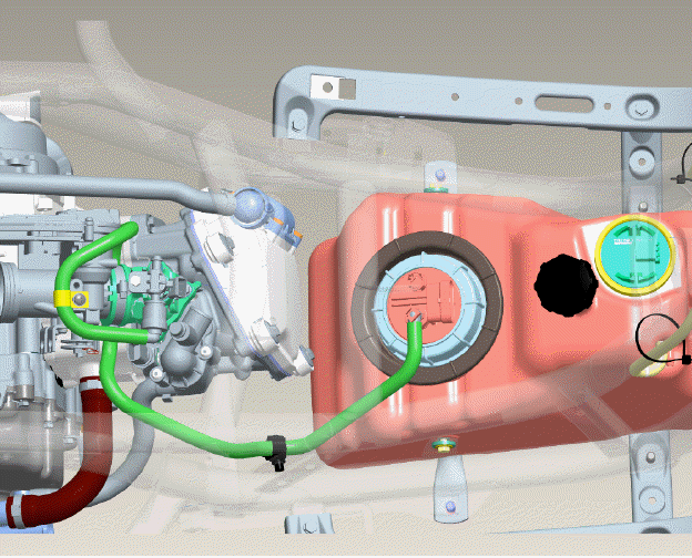
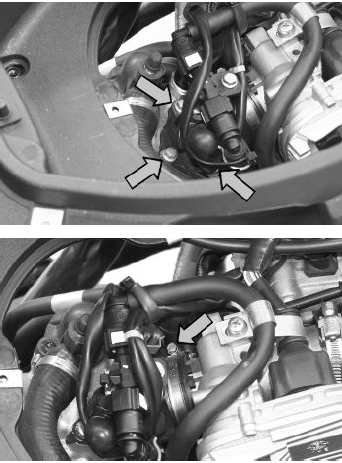
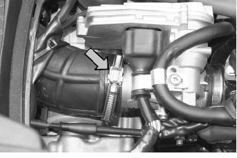
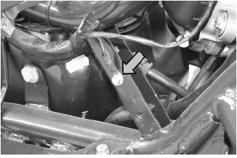
Remove the fuel piping clamping screw indicated in the figure.
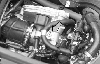
Remove the fast-release fittings from the injector support.
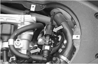
Remove the injector connector.
Remove the three screws fixing the manifold to the cylinder head and the clip fixing the throttle body to the manifold.
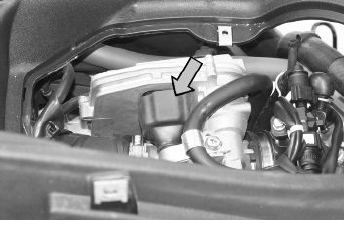
Remove the MIU ECU connector.
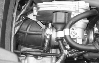
Remove the clip fixing the throttle body to the air cleaner bellows.
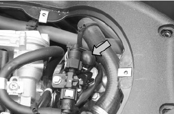
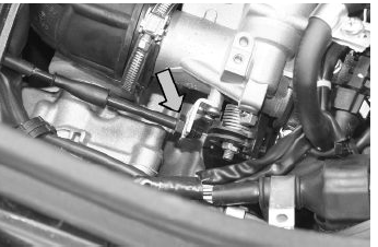
Remove the gas command fitting as indicated in the picture
Refitting the butterfly valve
To refit, perform the operations in the reverse order from the removal operations being careful to position the clip fixing the throttle body to the air filter bellows at 45º as shown in the photograph.
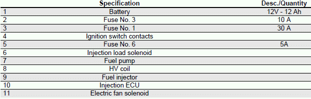
Pump supply circuit
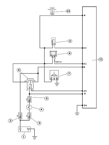
INJECTION LOADS
When switched to "ON", the fuel pump starts to rotate for 2 seconds and then stops. When the engine starts, in the presence of rpm timing signal the pump is continuously supplied.
ELECTRICAL DATA
- Pump winding resistance - 1.5 Ohm
- Input current during normal functioning 1.4 to 1.8 A
- Input current to the closed hydraulic circuit - 2 A (to be checked with specific tool for fuel pressure control, choking the circuit on the return pipe)
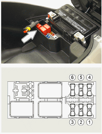
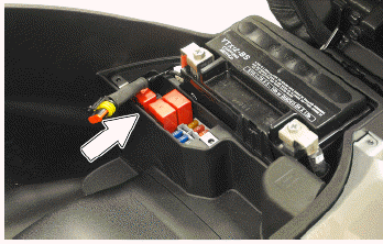
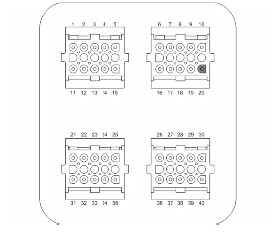
Check function of fuses No. 3 and 6 for the ECU and injection load solenoid.
Check the efficiency of the injection load solenoid.
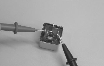
Check the resistance of the energising coil between pins 86 and 85: 40 to 80 Ohm
Apply a voltage of 12V to pins 86 and 85; make sure that there is continuity between pins 30 and 87 of the relay.
WARNING
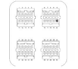
TO INDICATE THE RELAY OF THE DESIRED FUNCTION, REFER TO THE PIN-CABLE COLOUR RELATIONSHIP WITH THE ATTACHED ELECTRIC SYSTEM DIAGRAM.
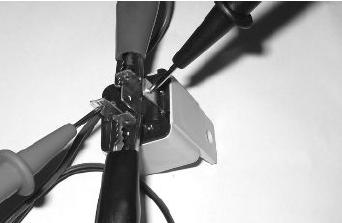
Check the power supply line of the injection load solenoid energising coil: after switching to "ON", make sure there is battery voltage, for 2 seconds, between the Red-White cable and the Black-Purple cable of the solenoid base. If there is not, check the continuity of the Red-White cable between the fuse box and the solenoid base and of the Black- Purple cable between the pin 20 of the control unit and the solenoid base.
N.B.
CONTINUITY TESTS MUST BE CARRIED OUT WITH THE COMPONENTS DISCONNECTED. (RELAYS, CONTROL UNIT, FUSES ETC.).
Check for continuous voltage between the grey/ black cable of the solenoid base and ground. If no voltage is measured, check continuity of the Grey/ Black cable between the fuse box (No. 3, 5A) and the solenoid base.
N.B.
CONTINUITY TESTS MUST BE CARRIED OUT WITH THE COMPONENTS DISCONNECTED. (RELAYS, CONTROL UNIT, FUSES ETC.).
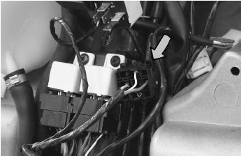
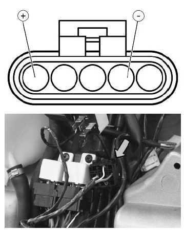
After switching to "ON", check that there is battery voltage, for about 2 seconds, between the Black- Green cable of the pump connector and the ground lead with the pump connector disconnected.
Otherwise, check the continuity of the Black- Green cable between the pump connector and the relay base.
Check the efficiency of the ground line of the fuel pump by measuring the continuity between the pump connector black cable, system side, and the ground.
If, when switching to "ON", the pump continues to turn after 2 seconds of activation, check, with the control unit disconnected and the injection load relay disconnected, that the Black-Purple cable (pin 20 on the interface wiring) is insulated from the ground.
Specific tooling
020331Y Digital multimeter
See also:
 PIAGGIO Beverly 300ie - Service manual > Circuit leak test
Install the specific tool for checking the fuel pressure, with the pipe fitted with the gauge. Check during regular operation by placing the appropriate tool between the pump and the injector.


