 Suzuki Burgman 400 - Service manual > Component Location
Electrical Components Location
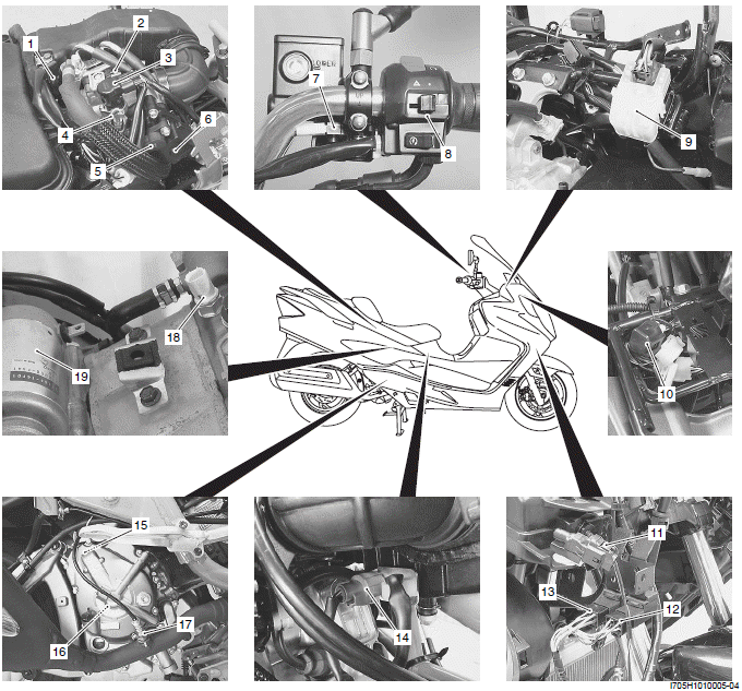
- Fuel injector
- IAP sensor
- ISC valve
- TP sensor
- STP sensor
- STVA
- Front brake switch
- Right handlebar switch
- Starter relay
- Mode select switch coupler
- Ambient air temperature sensor
- Brake-lock relay
- Fuel pump relay
- IAT sensor
- CKP sensor
- Generator
- HO2 sensor
- ECT sensor
- Starter motor
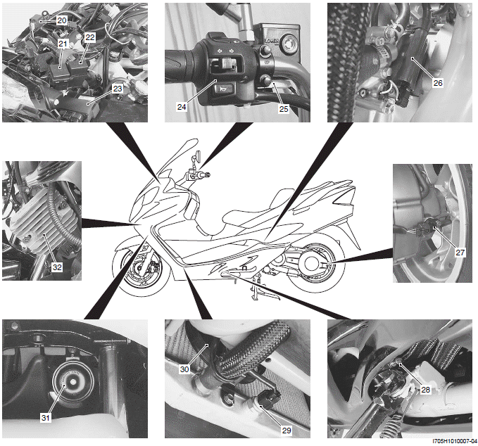
- TO sensor
- Fuse box
- Turn signal/Side-stand relay
- ECM
- Left handlebar switch
- Rear brake switch
- Ignition coil
- Speed sensor
- Side-stand switch
- Cooing fan thermo-switch
- Cooing fan
- Horn
- Regulator/rectifier
Specifications
NOTE These specifications are subject to change without notice.
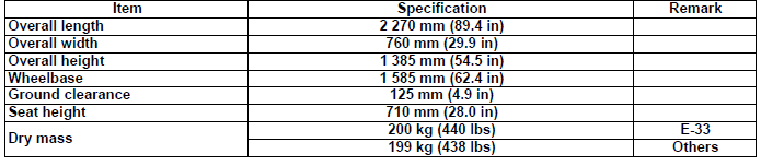
Dimensions and Dry Mass
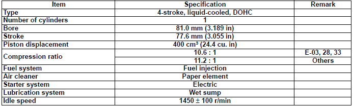
Engine
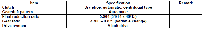
Drive Train
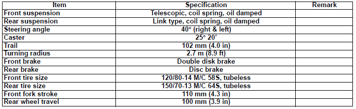
Chassis
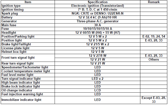
Electrical
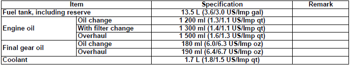
Capacities
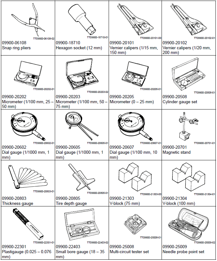
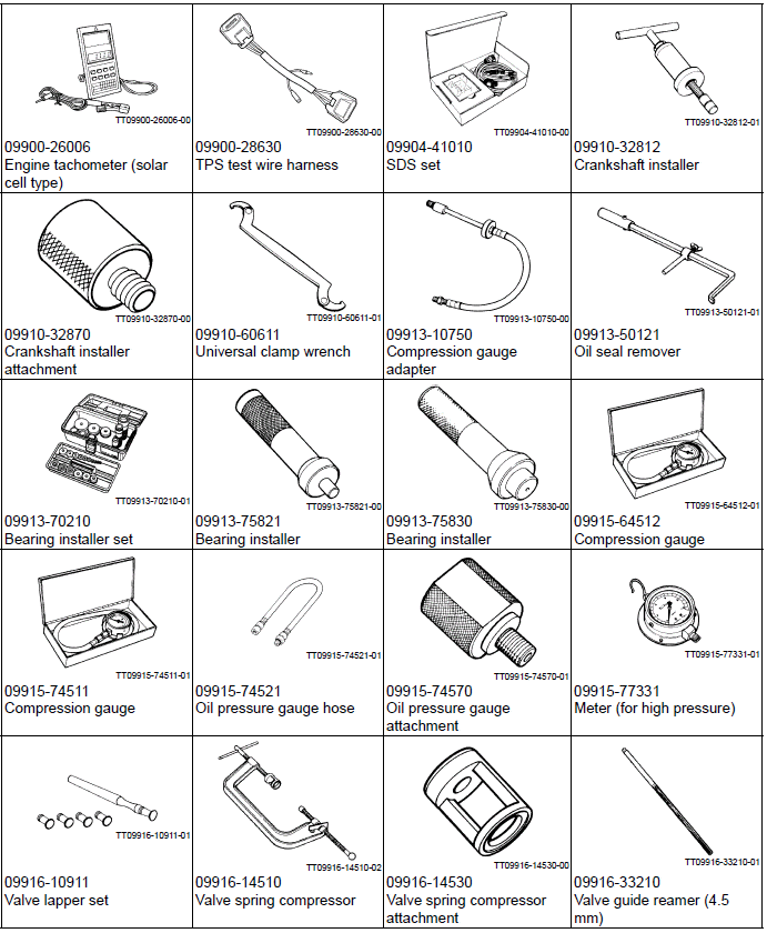
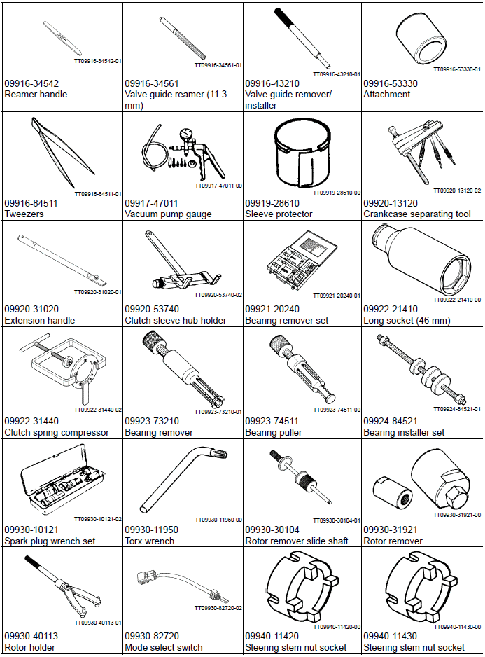
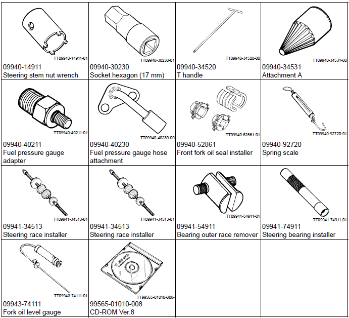
Special Tools and Equipment
Special Tool
See also:
 Suzuki Burgman 400 - Service manual > Fuel / Oil / Engine Coolant Recommendation
Fuel (For USA and Canada) Use only unleaded gasoline of at least 87 pump octane (R/2 + M/2) or 91 octane or higher rated by the research method. Gasoline containing MTBE (Methyl Tertiary Butyl Ether), less than 10% ethanol, or less than 5% methanol with appropriate cosolvents and corrosion inhibitor is permissible.
Suzuki Burgman 400 - Service manual > Maintenance and Lubrication
Precautions Precautions for Maintenance The "Periodic Maintenance Schedule Chart" lists the recommended intervals for all the required periodic service work necessary to keep the motorcycle operating at peak performance and economy. Maintenance intervals are expressed in terms of kilometers, miles and months for your convenience.


