 Vespa GTS Super 300 ie - Service manual > Components location
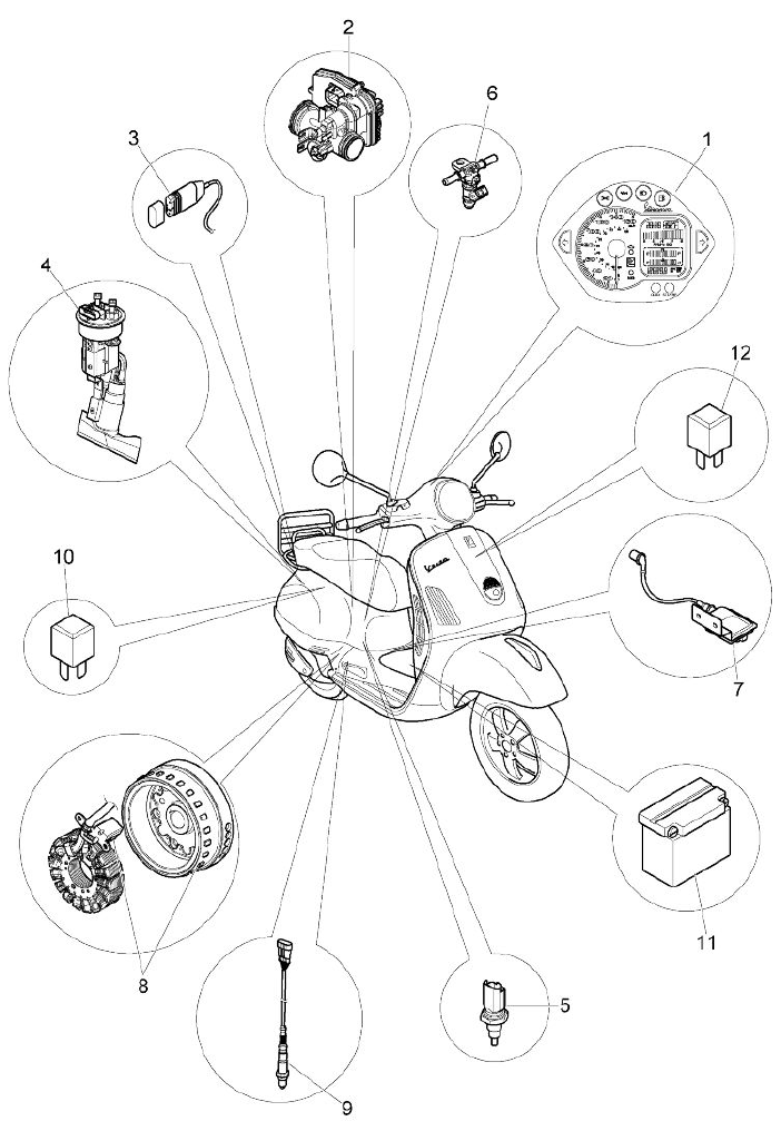
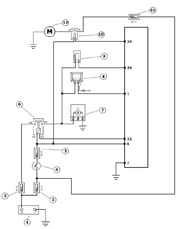
COMPONENT LAYOUT
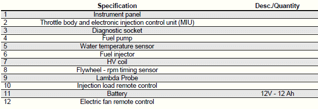
HT coil
- Battery 12V
- Fuse No. 2 of 15A
- 30A fuse No. 1
- Key switch contacts
- Fuse No. 5 of 7.5A
- Injection load remote control
- Fuel pump
- H.V. coil.
- Fuel injector
- Electric fan solenoid
The ignition system is integrated with the injection and it is a high-efficiency inductive type ignition.
The control unit manages two significant parameters:
- Ignition advance
This is optimised at once according to the engine revs, engine load, temperature and ambient pressure.
With idle engine, it is optimised to obtain the stabilisation of the speed at 1450 +- 50 R/1'.
- Magnetisation time
The coil magnetisation time is controlled by the control unit. The ignition power is increased during the engine start-up phase.
The injection system recognises the four-stroke cycle so the ignition is only commanded in the compression phase.
Specific tooling
020331Y Digital multimeter
Check that the injection load 15A fuse No. 2 works properly.
Check that the 7.5A fuse No. 5 for live control unit power works properly.
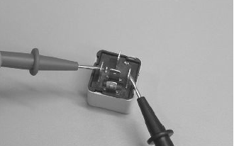
Check the efficiency of the injection load solenoid.
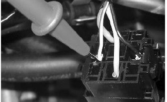
Check the resistance of the energising coil between pins 86 and 85: 40 to 80 Ohm Apply a voltage of 12V to pins 86 and 85; make sure that there is continuity between pins 30 and 87 of the relay.
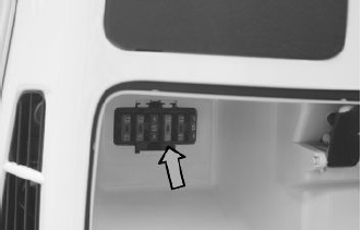
Check the power supply line of the injection load solenoid energising coil: after switching to "ON", make sure there is battery voltage, for two seconds, between the Red-White cable and Black- Purple cable of the solenoid control base. If there is not, check the continuity of the Red-White cable between the fuse box under the saddle hinge and the remote control base and of the Black-Purple cable between pin 22 of the control unit and the remote control base.
N.B.
CONTINUITY TESTS MUST BE CARRIED OUT WITH THE COMPONENTS DISCONNECTED. (RELAYS, CONTROL UNIT, FUSES ETC.).
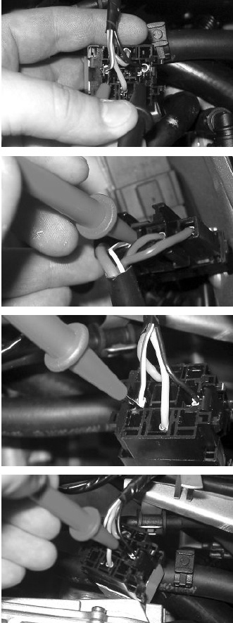
Check the presence of fixed voltage between the grey/black cable of the remote control base and earth. If there is none check the continuity of the grey/black cable between the fuse box (No. 2 15 A) and the remote control base.
N.B.
CONTINUITY TESTS MUST BE CARRIED OUT WITH THE COMPONENTS DISCONNECTED. (RELAYS, CONTROL UNIT, FUSES ETC.).
Zeroing the throttle
Resetting the throttle valve position signal (TPS reset)
The MIU control unit is supplied with a throttle valve position sensor that is pre-calibrated.
Pre-calibration entails regulating the minimum opening of the throttle valve to obtain a certain flow of air under pre-set reference conditions.
Pre-calibration ensures optimal air flow to control idling.
This regulation must not be tampered with in any way whatsoever.
The injection system will complete the management of the idling through the Stepper motor and the variation of the ignition advance.
The throttle body after the pre-calibration has an opened valve with an angle that can vary depending on the tolerances of the machining of the pipe and the valve itself.
The valve position sensor can also assume various fitting positions. For these reasons the mV of the sensor with the valve at idle can vary from one throttle body to another.
To obtain the optimum fuel mixture, especially at small openings of the throttle valve, it is essential to match the throttle body with the control unit following the procedure known as TPS resetting.
With this operation we inform the control unit, as the starting point, of the mV value corresponding to the pre-calibrated position.
To reset, proceed as follows.
Connect the diagnostic tester.
Switch to "ON".
Select the functions of the diagnostic tester on "TPS RESET".
Specific tooling
020922Y Diagnosis Tool
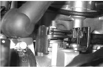
Make sure that the throttle valve with the control is supporting the stop screw.
Guaranteeing that this position will be kept, send a confirmation for the TPS reset procedure.
Reset should be performed in the following cases:
- on first fitting.
- if the injection control unit is replaced.
N.B.
THE TPS RESET PROCEDURE MUST NOT BE CARRIED OUT WITH A USED THROTTLE BODY BECAUSE POSSIBLE VALVE WEAR AND STOP WEAR FOR THE MINIMUM OPENING MAKE THE AIR FLOW DIFFERENTLY FROM THAT OF PRE-CALIBRATION.
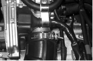
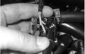
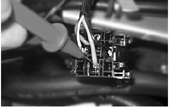
Given that the TPS resetting is also done when the control unit is replaced, place the control unit - filter box bellows at 45º during the refitting operation as shown in the picture.
Impianto elettroventilatore
- Battery 12V
- Fuse No. 2 of 15A
- 30A fuse No. 1
- Key switch contacts
- Fuse No. 5 of 7.5A
- Injection load relay
- Fuel pump
- H.V. coil.
- Fuel injector
- Electric fan solenoid
- 15A fuse No. 3
- Electric fan motor
Check that the 7.5A fuse No. 5 works properly
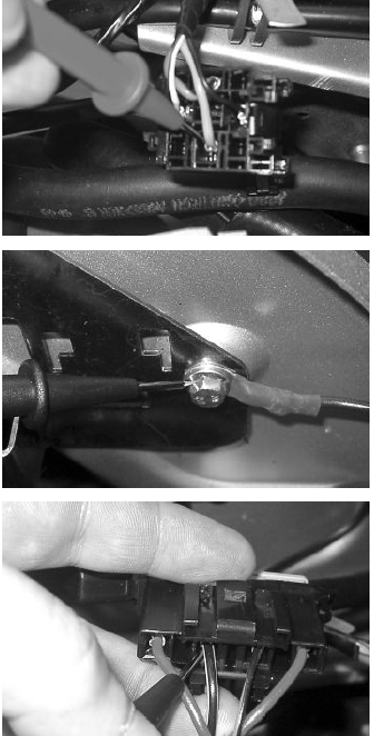
With the key switch set to ON, check if there is +12 V battery voltage between the RED - WHITE cable of the electric fan remote control and the ground connection.
Check if the RED - WHITE cable between the fuse box (under the saddle) and the electric fan remote control base is not interrupted
Using a diagnosis hand-held computer, carry out an active diagnosis for the "ELECTRIC FAN".
Check if there is battery voltage at pins 85 - 86 of the electric fan remote control
Check if the BLUE - YELLOW cable between the control unit pin 8 and the electric fan remote control base is not interrupted
Check the 15A Fuse No. 3
Check if there is +12 V voltage between the GREY cable of the electric fan remote control base and the ground connection.
Check if the RED - BLACK cable between the fuse box under the seat and the fuse box in the glovebox compartment is not interrupted.
Check if the GREY cable between the fuse box in the glove-box compartment and the electric fan remote control base is not interrupted.
Check if the RED cable between the electric fan remote control base and the electric fan motor is not interrupted.
Check that the electric fan motor is earthed.
See also:
 Vespa GTS Super 300 ie - Service manual > Fuel supply system
The fuel supply circuit includes the electric pump, the filter, the pressure regulator, the electro-injector and the fuel delivery pipes. The electrical pump is located in the tank from which the fuel is pumped and sent to the injector through the filter.


