 Vespa GTS Super 300 ie - Service manual > Fuel supply system
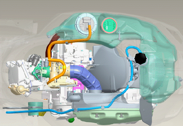
The fuel supply circuit includes the electric pump, the filter, the pressure regulator, the electro-injector and the fuel delivery pipes.
The electrical pump is located in the tank from which the fuel is pumped and sent to the injector through the filter.
The pressure is controlled by the pressure regulator situated in the pump assembly in the tank.
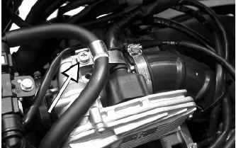
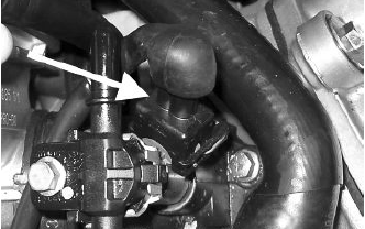
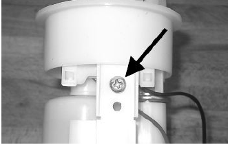
Removing the butterfly valve
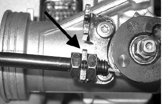
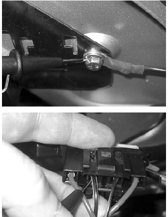
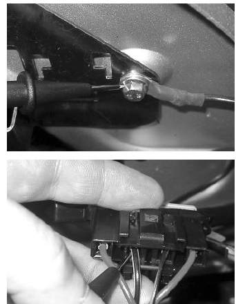
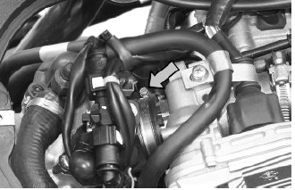
Remove the fuel piping clamping screw indicated in the figure.
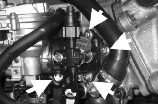
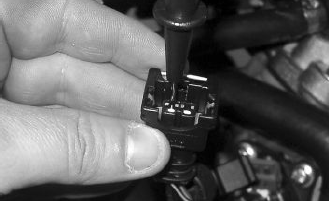
Remove the fast-release fittings from the injector support.
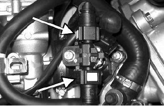
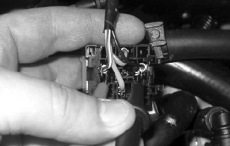
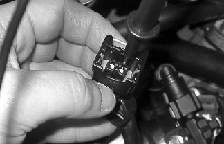
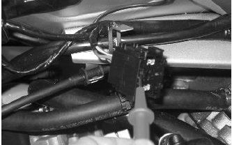
Remove the injector connector.
Remove the three screws fixing the manifold to the cylinder head and the clip fixing the throttle body to the manifold.
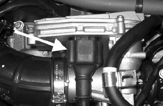
Remove the MIU ECU connector.
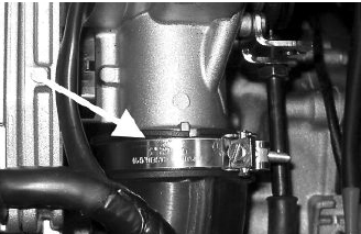
Remove the clip fixing the throttle body to the air cleaner bellows.
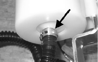
Remove the gas command fitting as indicated in the picture
Refitting the butterfly valve
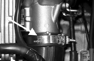
To refit, perform the operations in the reverse order from the removal operations being careful to position the clip fixing the throttle body to the air filter bellows at 45º as shown in the photograph.
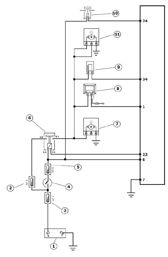
Pump supply circuit
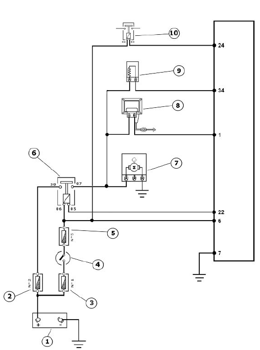
- Battery 12V
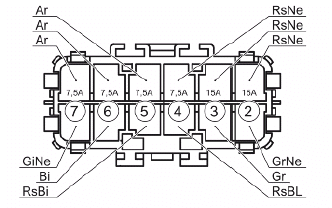
- Fuse No. 2 of 15A
- 30A fuse No. 1
- Key switch contacts
- Fuse No. 5 of 7.5A
- Injection load remote control
- Fuel pump
- H.V. coil.
- Fuel injector
- Electric fan solenoid
When switched to "ON", the fuel pump starts to rotate for two seconds and then stops. When the engine starts, in the presence of rpm timing signal the pump is continuously supplied.
ELECTRICAL DATA
- Pump winding resistance - 1.5 Ohm
- Input current during regular operation 1.4 - 1.8 A
- Input current to the closed hydraulic circuit - 2 A (to be checked with appropriate tool for fuel pressure control choking the circuit on the return pipe)
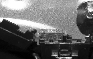
Check that the injection load 15A fuse No. 2 works properly.
Check that the 7.5A fuse No. 5 for live control unit power works properly.
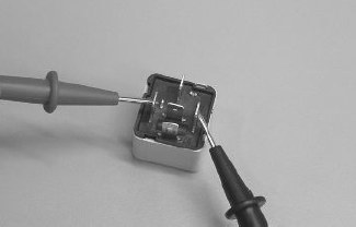
Check the efficiency of the injection load solenoid.
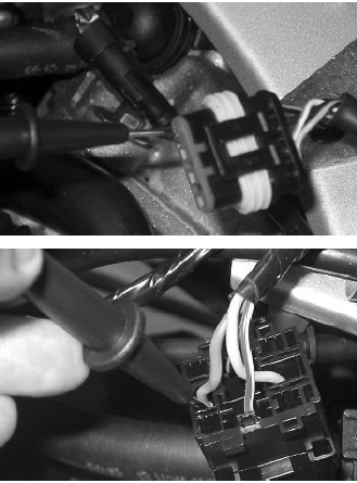
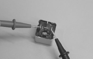
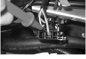
Check the resistance of the energising coil between pins 86 and 85: 40 to 80 Ohm
Apply a voltage of 12V to pins 86 and 85; make sure that there is continuity between pins 30 and 87 of the relay.
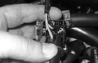
Check the power supply line of the injection load solenoid energising coil: after switching to "ON", make sure there is battery voltage, for two seconds, between the Red-White cable and Black- Purple cable of the solenoid control base. If there is not, check the continuity of the Red-White cable between the fuse box under the saddle hinge and the remote control base and of the Black-Purple cable between pin 22 of the control unit and the remote control base.
N.B.
CONTINUITY TESTS MUST BE CARRIED OUT WITH THE COMPONENTS DISCONNECTED. (RELAYS, CONTROL UNIT, FUSES ETC.).
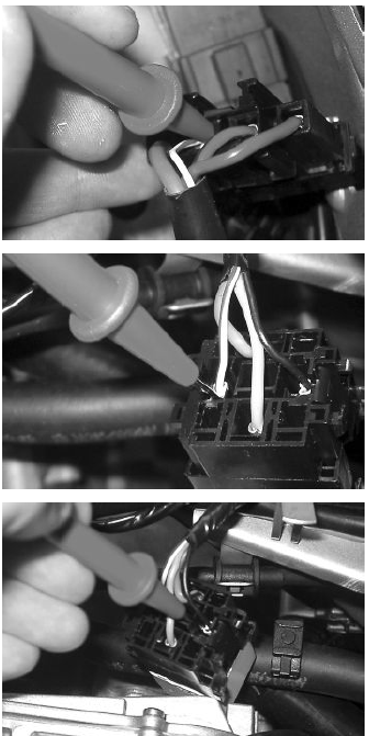
Check the presence of fixed voltage between the grey/black cable of the remote control base and earth. If there is none check the continuity of the grey/black cable between the fuse box (No. 2 15 A) and the remote control base.
N.B.
CONTINUITY TESTS MUST BE CARRIED OUT WITH THE COMPONENTS DISCONNECTED. (RELAYS, CONTROL UNIT, FUSES ETC.).
Check, on switching to "ON", that there is battery voltage, for about two seconds, to the Black-Green cable of the pump connector and ground with pump connector disconnected. Otherwise, check the continuity of the Black-Green cable between the pump connector and the remote control base.
Check the efficiency of the ground line of the fuel pump by measuring the continuity between the pump connector black cable, system side, and the ground.
If, when switching to "ON", the pump continues to turn after two seconds of activation, check, with the control unit disconnected and the injection load remote control disconnected, that the Black-Purple cable (pin 20 on the interface wiring) is insulated from the ground.
Specific tooling
020331Y Digital multimeter
Circuit leak test
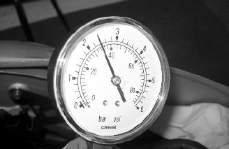
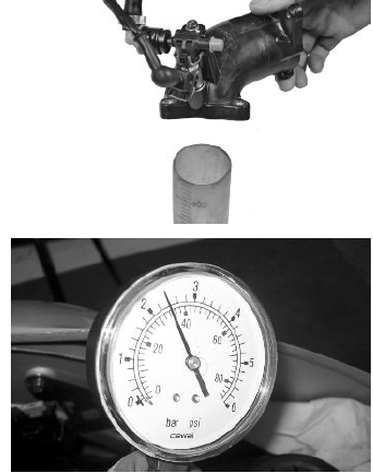
Install the specific tool for checking the fuel pressure, with the pipe fitted with the gauge.
Check during regular operation by placing the appropriate tool between the pump and the injector.
With the battery voltage> 12 V check that the fuel pressure is 2.5 BAR and that the input current is 1.4 to 1.8 A
With the battery voltage > 12 V, check the capacity of the pump flow rate by disconnecting from the injector the pipe equipped with the pressure gauge of the appropriate tool. Make a graded burette available with a flowrate of approximately 1 L. Rotate the pump using the active diagnosis of the palm top computer. Using a pair of long flat needle-nose pliers, choke the fuel pipe making the pressure stabilise at approx. 2.5 BAR. Check that, in fifteen seconds, the pump has a flowrate of around 110cc.
Specific tooling
020480Y Petrol pressure check kit
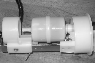
Fuel filter check
Disconnect the terminals from the electric pump
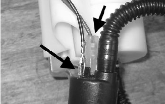
Remove the screw shown in the picture
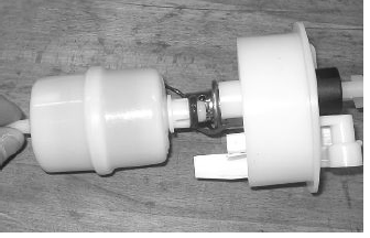
Remove the clip fixing the piping to the filter shown in the picture
Separate the lower part of the pump mounting as shown in the picture.
Remove the filter from the pump mounting
Inspecting the injector circuit
- Battery 12V
- Fuse No. 2 of 15A
- 30A fuse No. 1
- Key switch contacts
- Fuse No. 5 of 7.5A
- Injection load relay
- Fuel pump
- H.V. coil.
- Fuel injector
- Electric fan solenoid
- Coolant electric pump
Check the resistance at the injector ends: 14.5 +- 5% Ohm
Check that the injection load 15A fuse No. 2 works properly.
Check that the 7.5A fuse No. 5 for live control unit power works properly.
Check the efficiency of the injection load solenoid.
Check the resistance of the energising coil between pins 86 and 85: 40 to 80 Ohm
Apply a voltage of 12V to pins 86 and 85; make sure that there is continuity between pins 30 and 87 of the relay.
Check the power supply line of the injection load solenoid energising coil: after switching to "ON", make sure there is battery voltage, for two seconds, between the Red-White cable and Black- Purple cable of the solenoid control base. If there is not, check the continuity of the Red-White cable between the fuse box under the saddle hinge and the remote control base and of the Black-Purple cable between pin 22 of the control unit and the remote control base.
N.B.
CONTINUITY TESTS MUST BE CARRIED OUT WITH THE COMPONENTS DISCONNECTED. (RELAYS, CONTROL UNIT, FUSES ETC.).

Check the presence of fixed voltage between the grey/black cable of the remote control base and earth. If there is none check the continuity of the grey/black cable between the fuse box (No. 2 15 A) and the remote control base.
N.B.
CONTINUITY TESTS MUST BE CARRIED OUT WITH THE COMPONENTS DISCONNECTED. (RELAYS, CONTROL UNIT, FUSES ETC.).
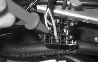
With the control unit and the injector disconnected, check the continuity of the Red-Yellow cable between pin 34 of the interface wiring and the injector connector
Switch to "ON" and check if there is voltage, with injector disconnected and control unit connected, between the Black-Green cable of the injector connector and the ground lead
With injector disconnected and the injector load relay disconnected, check the continuity of the Black-Green cable between the injector connector and solenoid base.
Inspecting the injector hydraulics
To carry out the injector check, remove the intake manifold by removing the three clamping screws at the head and the clip connecting the control unit to the manifold.
Install the appropriate tool for checking fuel pressure and position the manifold over a container graduated by at least 100 cm³. Connect the injector with the cable making up part of the supply for the injection tester. Connect the clamps of the cable to an auxiliary battery. Activate the fuel pump with the active diagnosis. Check that, within fifteen seconds, approximately 40 cm³ of fuel is dispensed with an adjustment pressure of approximately 2.5 BAR.
Specific tooling
020480Y Petrol pressure check kit
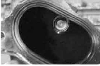
Proceed with the injector seal test.
Dry the injector outlet with a blast of compressed air. Activate the fuel pump. Wait for one minute, making sure there are no leaks coming from the injector. Slight oozing is normal.
Value limit = 1 drop per minute
See also:
 Vespa GTS Super 300 ie - Service manual > Precautions
1. Before fixing any part of the injection system, check to see if there are any registered faults. Do not disconnect the battery before checking for faults. 2. The fuel system is pressurised at 250 kPa (2.5 BAR). Before disconnecting the fast-release fitting of the fuel supply pipe, check that there are no naked flames. Do not smoke. Act with caution to avoid spraying fuel to your eyes.
Vespa GTS Super 300 ie - Service manual > Components location
COMPONENT LAYOUT


