 Vespa GTS Super 300 ie - Service manual > Precautions
1. Before fixing any part of the injection system, check to see if there are any registered faults. Do not disconnect the battery before checking for faults.
2. The fuel system is pressurised at 250 kPa (2.5 BAR). Before disconnecting the fast-release fitting of the fuel supply pipe, check that there are no naked flames. Do not smoke. Act with caution to avoid spraying fuel to your eyes.
3. When fixing electric components, operate with the battery connected only when actually required.
4. When functional checks are performed, check that the battery voltage is over 12V.
5. Before any attempt to start the vehicle, check to make sure there is at least two litres of fuel in the tank. Failure to respect this norm will damage the fuel pump.
6. If the vehicle is expected to remain unused for a long time, refill the tank up to a little over half the level. This will ensure the pump will be covered by fuel.
7. When washing the vehicle, be careful with the electric components and cable harnesses.
8. When an ignition problem is detected, start the checks from the battery and the injection system connections.
9. Before disconnecting the MIU ECU connector, perform the following steps in the order shown:
- Set the switch to "OFF"
- Disconnect the battery
Failure to respect this norm may damage the control unit.
10. Do not invert the poles when fitting the battery.
11. To avoid causing any damage, disconnect and reconnect the MIU system connectors only if required.
Before reconnecting, check that the connectors are dry.
12. When carrying out electric inspections, do not force the tester probes into the connectors. Do not take measurements not specifically foreseen by the manual.
13. At the end of every check performed with the diagnostic tester, remember to protect the system connector with its cap. Failure to observe this precaution may damage the MIU control unit.
14. Before reconnecting the quick couplers of the power supply system, check that the terminals are perfectly clean.
Troubleshooting tips
1 - A MIU failure is more likely to be due to the connections than to the components.
Before troubleshooting the MIU system, carry out the following checks:
- Electrical power supply
- Battery voltage
- Burnt fuse
- Remote control switches
- Connectors
- Chassis ground
- Fuel system
- Faulty fuel pump
- Dirty fuel filter
- Ignition system
- Faulty spark plug
- Faulty coil
- Faulty screened cap
- Intake circuit
- Air filter dirty
- Dirty by-pass circuit
- Faulty stepper motor
- Other
- Wrong distribution timing
- Incorrect idle speed carburetion
- Incorrect reset of the throttle valve position sensor
2 - MIU system faults may be caused by loose connectors. Make sure that all connections have been correctly made.
Check the connectors taking into consideration the following point:
- check that the terminals are not bent.
- check that the connectors have been properly connected.
- Check whether the malfunction can be fixed by shaking the connector slightly.
3 - Check the entire system before replacing the MIUIf the fault is fixed by replacing the MIU, install the original control unit again and check if the fault occurs again.
4 - Use a multimeter with an internal resistance of more than 10K Ohm /V when troubleshooting. Instruments that are not suitable might damage the MIU central control unit. Use instruments with definitions over 0.1V and 0.5 W , the precision must be greater than 2%.
Terminals setup
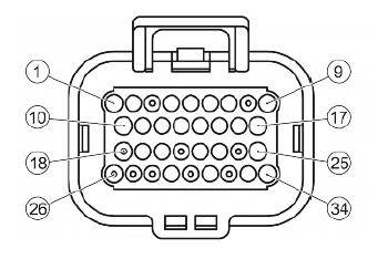
ELECTRONIC CONTROL UNIT CONNECTOR
- H.V. COIL (Pink-Black)
- Not connected
- Not connected
- Engine switch (Grey-Green)
- Not connected
- Live supply (Red-White)
- Ground No. 1 (Black)
- Not connected
- Battery-powered (Grey-Black)
- Start-up signal (Orange-Blue)
- Lambda probe positive (Sky blue-Black)
- Lambda probe negative (White-Green)
- Water temperature sensor (Sky blue-Green)
- Immobilizer aerial (Orange-White)
- Not connected
- K serial line (Purple-White)
- Immobilizer (Red-Green)
- Not connected
- Side stand (Grey-Green)
- Speed sensor negative (Brown)
- Not connected
- Injection load relay (Black-Purple)
- Not connected
- Consent to radiator electric fan (Blue-Yellow)
- Injection warning light (Brown-Black)
- Not connected
- Not connected
- Not connected
- Engine speed sensor positive (Red)
- Not connected
- Lambda probe heater (White)
- Not connected
- Low beam lights automatic ignition enabling (White-Black)
- Fuel injector (Red-Yellow)
EMS circuit diagram
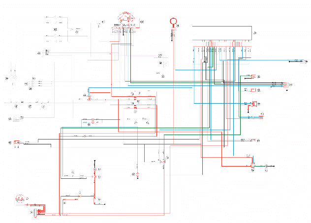
- Battery 12V - 12 Ah
- Starter relay
- Starter motor
- Starter button
- Voltage regulator
- Magneto flywheel
- Fuse No. 1 - 30A
- Fuse No. 5 - 7.5A
- Fuse No. 2 - 15A
- Fuses No. 6 - 7.5A
- Fuse No. 3 - 15A
- Fuse No. 4 - 7.5A
- Key switch contacts
- Engine stop switch
- N.2 stop buttons
- Brake lamp 12v-16w
- Injection load relay
- Electric fan remote control
- Radiator electric fan
- Lambda probe
- Engine speed sensor
- H.V. coil.
- Fuel injector
- Engine temperature sensor
- Fuel pump
- Diagnosis socket
- Injection electronic control unit
- Immobilizer antenna
- Instrument panel
- Headlight relay
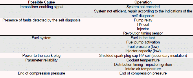
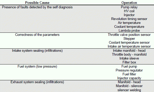
Troubleshooting procedure
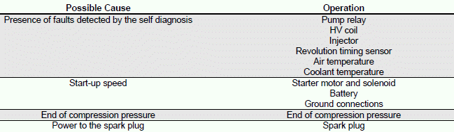
Engine does not start
ENGINE DOES NOT START IF ONLY PULLED
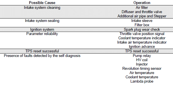
Starting difficulties
ENGINE STARTER PROBLEMS
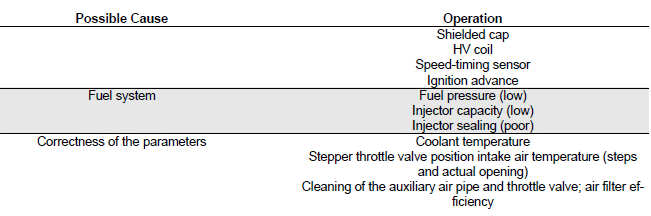
Engine stops at idle
ENGINE DOES NOT IDLE/ IDLING IS UNSTABLE/ IDLING TOO LOW
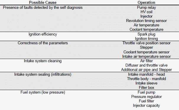
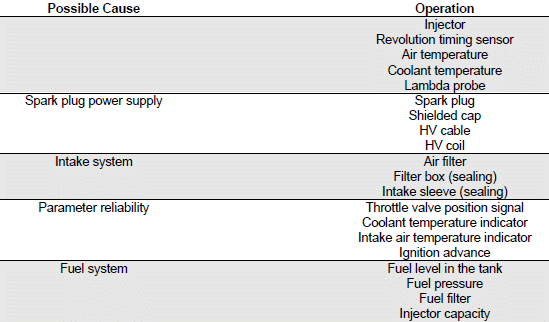
Engine does not rev down
ENGINE DOES NOT RETURN TO IDLING SPEED/IDLING SPEED TOO HIGH
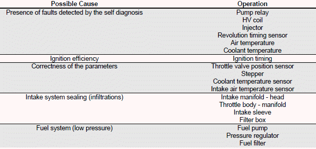
Exhaust backfires in deceleration
EXHAUST BACKFIRES WHEN DECELERATING
Engine revs irregularly
ENGINE IRREGULAR PERFORMANCE WITH VALVE SLIGHTLY OPEN
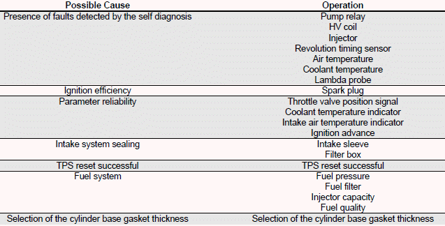
Poor performance at full throttle
POOR ENGINE PERFORMANCE AT FULL POWER/ ENGINE IRREGULAR PERFORMANCE ON PICKUP

Engine knocking
PRESENCE OF KNOCKING (COMBUSTION SHOCKS)
See also:
 Vespa GTS Super 300 ie - Service manual > Injection
COMPONENT TRANSPOSITION
Vespa GTS Super 300 ie - Service manual > Fuel supply system
The fuel supply circuit includes the electric pump, the filter, the pressure regulator, the electro-injector and the fuel delivery pipes. The electrical pump is located in the tank from which the fuel is pumped and sent to the injector through the filter.


