 PIAGGIO Beverly 300ie - Service manual > Connectors
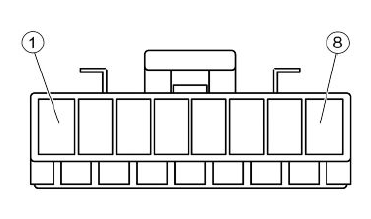
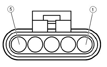
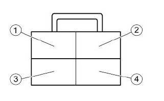
INSTRUMENT PANEL CONNECTOR "A"
- Left turn indicator warning light (Pink)
- Immobilizer (Red-Green)
- Battery-powered (Red-Black)
- Coolant temperature sensor (Green-Yellow)
- Not connected
- Fuel level transmitter (White-Green)
- Right turn indicator warning light (White-Blue)
- Low fuel warning light (Grey-Black)
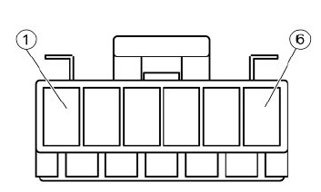
INSTRUMENT PANEL CONNECTOR "B"
- High-beam warning light (Violet)
- Ground lead (Black)
- Injection warning light (Brown-Black)
- Oil pressure sensor (Pink-White)
- Live power supply (White)
- Instrument panel lighting (Yellow-Black)
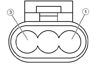
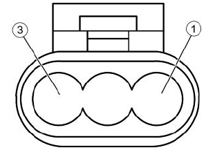
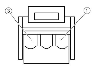
IMMOBILIZER AERIAL CONNECTOR
- Live power supply (Red-White)
- Ground lead (Black)
- Injection ECU (Orange-White)
FUEL PUMP CONNECTOR
- Not connected
- Ground lead (Black)
- Not connected
- Not connected
- Power from relay (Black-Green)
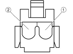
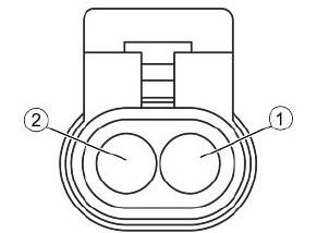
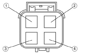
ELECTRIC FAN CONNECTOR
- Ground lead (Black)
- Power from solenoid (Red)
PICKUP CONNECTOR
- Engine speed sensor ECU positive (Red)
- Engine speed sensor ECU negative (Brown)
- Oil pressure sensor (White-Pink)
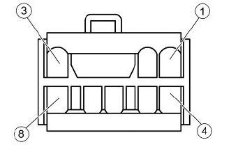
ANTITHEFT DEVICE PRE-INSTALLATION CONNECTOR
- Left turn indicator bulbs (Pink)
- Right turn indicator bulbs (White-Blue)
- Ground lead (Black)
- Battery-powered (Blue)
- Live power supply (White)
- Helmet compartment light (Red-Yellow)
- Not connected
- Not connected
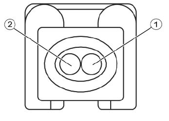
2-PIN CONNECTOR ONLY
- Sky blue-black positive from control unit
- White-Green negative from control unit
VOLTAGE REGULATOR CONNECTOR
- Battery positive (Red-Black)
- Ground lead (Black)
- Battery positive (Red-Black)
- Ground lead (Black)
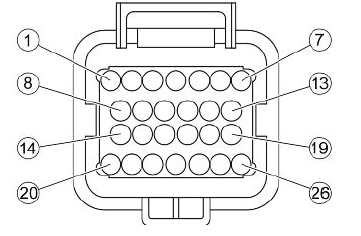
INJECTION ELECTRONIC CONTROL UNIT CONNECTOR
- Injection warning light (Brown-Black)
- Not connected
- Not connected
- Lambda probe negative (White-Green)
- Live power supply (Red-White)
- Battery-powered (Orange-Black)
- Immobilizer aerial (Orange-White)
- Electric fan solenoid (Blue-Yellow)
- Coolant temperature sensor (Sky blue-Green)
- Not connected
- Lambda probe positive (Sky blue-Black)
- Engine stop switch (Green-Black)
- Engine speed sensor positive (Red)
- Injector negative (Yellow-Red)
- Engine speed sensor negative (Brown)
- Diagnostics socket (Purple-White)
- Immobilizer LED (Red-Green)
- Side stand (Sky blue)
- Not connected
- Injection load solenoid (Black-Purple)
- Not connected
- HV coil negative (Pink-Black)
- Not connected
- Start-up solenoid (Orange-Blue)
- Fall sensor
- Ground lead (Black)
INJECTOR CONNECTOR
- Power from relay (Black-Green)
- Negative from control unit (Yellow-Red)
HV COIL CONNECTOR
- Negative from control unit (Red-Black)
- Power from relay (Black-Green)
FUEL LEVEL TRANSMITTER CONNECTOR
- Low fuel warning light (Grey-Black)
- Ground lead (Black)
- Fuel level indicator (White-Green)
COOLANT TEMPERATURE SENSOR CONNECTOR
- Ground lead (Grey-Green)
- Instrument panel (Green-Yellow)
- Injection ECU (Sky blue-Green)
- Ground lead (Black)
See also:
 PIAGGIO Beverly 300ie - Service manual > Battery installation
VRLA battery (valve-regulated lead-acid battery) Maintenance Free (MF) WARNING BATTERY ELECTROLYTE IS TOXIC AND IT MAY CAUSE SERIOUS BURNS. IT CONTAINS SULPHURIC ACID. AVOID CONTACT WITH YOUR EYES, SKIN AND CLOTHING. IN CASE OF CONTACT WITH YOUR EYES OR SKIN, RINSE WITH ABUNDANT WATER FOR ABOUT 15 MINUTES AND SEEK IMMEDIATE MEDICAL ATTENTION.
PIAGGIO Beverly 300ie - Service manual > Engine from vehicle
Exhaust assy. Removal Remove the RH footrest. Remove the Lambda probe from its support and disconnect it. Cut the fastening clamp on the lambda probe cable. Undo the two exhaust manifold fixings on the head. To unscrew the nuts that fix the silencer flange to the head properly, use a jointed wrench that allows, according to the travel direction, to get also at the right nut. That is difficult to do with a traditional straight wrench. Unscrew the three screws fastening the heat shield to the silencer; Unscrew the three screws "A" fastening the silencer to the silencer mounting bracket. Remove the full silencer unit. Remove the lambda probe from the manifold.


