 Suzuki Burgman 400 - Service manual > Cylinder Head Related Parts Inspection
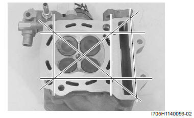
Cylinder Head Distortion
1) Decarbonize the combustion chambers.
2) Check the gasket surface of the cylinder head for distortion. Use a straightedge and thickness gauge.
Take clearance readings at several places. If readings exceed the service limit, replace the cylinder head.
Special tool
: 09900-20803 (Thickness gauge)
Cylinder head distortion
Service limit: 0.05 mm (0.002 in)
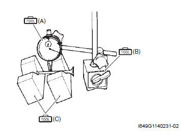
Valve Stem Runout
Support the valve using V-blocks, as shown, and check its runout using the dial gauge. If the runout exceeds the service limit, replace the valve.
Special tool
(A): 09900-20606 (Dial gauge (1/100 mm) )
(B): 09900-20701 (Magnetic stand)
(C): 09900-21304 (V-block (100 mm) )
Valve stem runout
Service limit: 0.05 mm (0.002 in)
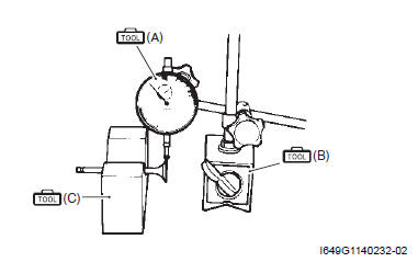
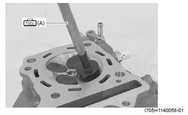
Valve Head Radial Runout
Place the dial gauge at a right angle to the valve head face and measure the valve head radial runout. If it measures more than the service limit, replace the valve.
Special tool
(A): 09900-20606 (Dial gauge (1/100 mm) )
(B): 09900-20701 (Magnetic stand)
(C): 09900-21304 (V-block (100 mm) )
Valve head radial runout
Service limit: 0.03 mm (0.001 in)
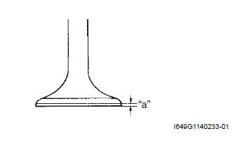
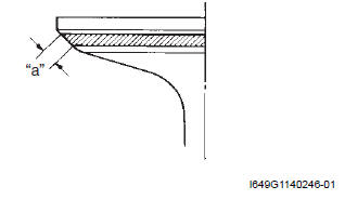
Valve Face Wear
Visually inspect each valve face for wear. Replace any valve with an abnormally worn face. The thickness of the valve face decreases as the face wears. Measure the valve face "a". If it is out of specification replace the valve with a new one.
Special tool : 09900-20102 (Vernier calipers)
Valve face thickness "a"
Service limit: 0.5 mm (0.02 in)
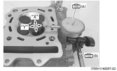
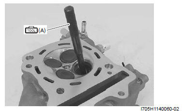
Valve Stem Deflection
Lift the valve about 10 mm (0.39 in) "a" from the valve seat. Measure the valve stem deflection in two directions, "X" and "Y", perpendicular to each other.
Position the dial gauge as shown. If the deflection exceeds the service limit, then determine whether the valve or the guide should be replaced with a new one.
Special tool
(A): 09900-20606 (Dial gauge (1/100 mm) )
(B): 09900-20701 (Magnetic stand)
Valve stem deflection (IN & EX)
Service limit: 0.35 mm (0.014 in)
Valve Stem Diameter
Measure the valve stem O.D. using the micrometer. If it is out of specification, replace the valve with a new one.
If the valve stem O.D. is within specification but the valve stem deflection is not, replace the valve guide. After replacing the valve or valve guide, recheck the deflection.
Special tool (A): 09900-20205 (Micrometer (0 - 25 mm) )
Valve stem O.D.
Standard (IN): 4.475 - 4.490 mm (0.1762 - 0.1768 in)
Standard (EX): 4.455 - 4.470 mm (0.1754 - 0.1760 in)
NOTE If valve guides have to be removed for replacement after inspecting related parts, carry out the steps shown in valve guide replacement. Refer to "Valve Guide Replacement".
Valve Springs
The force of the coil spring keeps the valve seat tight.
Weak-ened spring result in reduced engine power output, and often account for the chattering noise coming from the valve mechanism.
Check the valve spring for proper strength by measuring its free length and also by the force required to compress it.
If the spring length is less than the service limit, or if the force required to compress the spring does not fall within the range specified, replace the spring.
Special tool (A): 09900-20102 (Vernier calipers)
Valve spring free length (IN & EX)
Service limit: 38.6 mm (1.52 in)
Valve spring tension (IN & EX)
Standard: 137.3 N (14.0 kgf, 30.1 lbs) 33.35 mm (1.313 in)
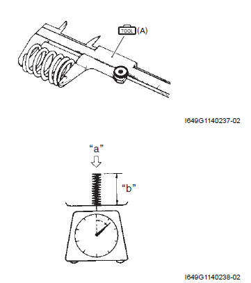
Tension "a" -137.3 N (14.0 kgf, 30.1 lbs)
Length "b" - 33.35 mm (1.313 in)
Valve Seat Width
1) Visually check for valve seat width on each valve face. If the valve face has worn abnormally, replace the valve.
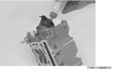
2) Coat the valve seat with a red lead (Prussian Blue) and set the valve in place.
3) Rotate the valve with light pressure.
Special tool (A): 09916-10911 (Valve lapper set)
4) Check that the transferred red lead (blue) on the valve face is uniform all around and in center of the valve face.
If the seat width "a" measured exceeds the standard value, or seat width is not uniform reface the seat using the seat cutter. Refer to "Valve Seat Repair".
Valve seat width "a"
Standard: 0.9 - 1.1 mm (0.035 - 0.043 in)
Valve Seat Sealing Condition
1) Clean and assemble the cylinder head and valve components.
2) Fill the intake and exhaust port with gasoline to check for leaks. If any leaks occur, inspect the valve seat and face for burrs or other things that could prevent the valve from sealing. Refer to "Valve Seat Repair".
! WARNING Always use extreme caution when handling gasoline.
NOTE After servicing the valve seats, be sure to check the valve clearance after the cylinder head has been reinstalled. Refer to "Valve Clearance Inspection and Adjustment".
Valve Guide Replacement
1) Remove the cylinder head. Refer to "Engine Top Side Disassembly".
2) Remove the valves. Refer to "Cylinder Head Disassembly and Reassembly ".
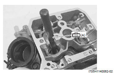
3) Using the valve guide remover, drive the valve guide out toward the intake or exhaust camshaft side.
Special tool (A): 09916-43210 (Valve guide remover/ installer)
NOTE
- Discard the removed valve guide sub assemblies.
- Only oversized valve guides are available as replacement parts. (Part No. 11115- 32C71)
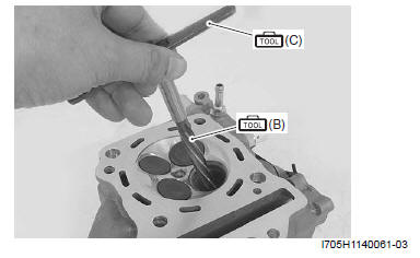
4) Refinish the valve guide holes in the cylinder head using the reamer and handle.
! CAUTION When refinishing or removing the reamer from the valve guide hole, always turn it clockwise.
Special tool
(B): 09916-34561 (Valve guide reamer (11.3 mm) )
(C): 09916-34542 (Reamer handle)
5) Cool down the new valve guides in a freezer for about one hour and heat the cylinder head to 100 - 150 ºC (212 - 302 ºF) with a hot plate.
! CAUTION Do not use a burner to heat the valve guide hole to prevent cylinder head distortion. 6) Apply engine oil to each valve guide (1) and valve guide hole.
7) Drive the guide into the guide hole using the valve guide installer.
! CAUTION Failure to oil the valve guide hole before driving the new guide into place may result in a damaged guide or head.
Special tool
(A): 09916-43210 (Valve guide remover/ installer)
(D): 09916-53330 (Attachment)
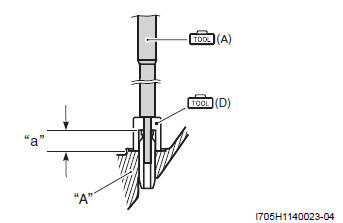
- Cylinder head
- 13.3 mm (0.52 in)
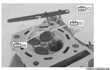
8) After installing the valve guides, refinish their guiding bores using the reamer. Be sure to clean and oil the guides after reaming.
Special tool
(C): 09916-34542 (Reamer handle)
(E): 09916-33210 (Valve guide reamer (4.5 mm) )
NOTE
- Be sure to cool down the cylinder head to ambient air temperature.
- Insert the reamer from the combustion chamber side and always turn the reamer handle clockwise.
9) Reassemble the cylinder head. Refer to "Cylinder Head Disassembly and Reassembly".
10) Install the cylinder head assembly. Refer to "Engine Top Side Assembly".
See also:
 Suzuki Burgman 400 - Service manual > Cylinder Head
Cylinder Head Disassembly and Reassembly Disassembly ! CAUTION Identify the position of each removed part. 1) Remove the tappet (1) and shim (2) by fingers or magnetic hand.
Suzuki Burgman 400 - Service manual > Valve Seat Repair
The valve seats (1) for both the intake and exhaust valves are machined to three different angles. The seat contact surface is cut at 45º.


