 Suzuki Burgman 400 - Service manual > Valve Seat Repair
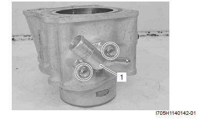
The valve seats (1) for both the intake and exhaust valves are machined to three different angles. The seat contact surface is cut at 45º.
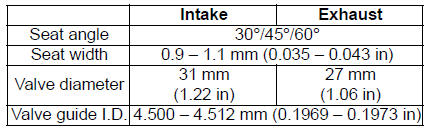
! CAUTION
- The valve seat contact area must be inspected after each nut.
- Do not use lapping compound after the final cut is made. The finished valve seat should have a velvety smooth finish but not a highly polished or shiny finish. This will provide a soft surface for the final seating of the valve which will occur during the first few seconds of engine operation.
NOTE After servicing the valve seats, be sure to check the valve clearance after the cylinder head has been reinstalled. Refer to "Valve Clearance Inspection and Adjustment ".
Cylinder
Cylinder Disassembly and Assembly
Refer to "Engine Top Side Disassembly" and "Engine Top Side Assembly".
Disassembly
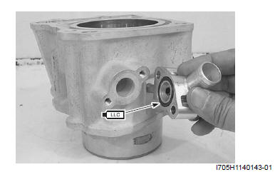
- Remove the water inlet connector (1).
Assembly
- Apply engine coolant to the O-ring.
! CAUTION Replace the O-ring with a new one.
Tightening torque
Water inlet connector bolt: 10 N*m (1.0 kgf-m, 7.0 lb-ft)
Cylinder Inspection
Refer to "Engine Top Side Disassembly".
Refer to "Engine Top Side Assembly".
Cylinder Distortion
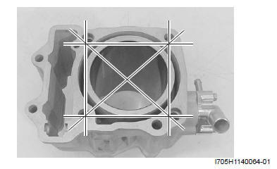
Check the gasket surface of the cylinder for distortion.
Use a straightedge and thickness gauge. Take clearance readings at several places. If any reading exceeds the service limit, replace the cylinder.
Special tool : 09900-20803 (Thickness gauge)
Cylinder distortion
Service limit: 0.05 mm (0.002 in)
Cylinder Bore
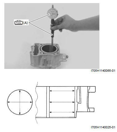
- Inspect the cylinder wall for any scratches, nicks or other damage.
- Measure the cylinder bore diameter at six place.
Special tool (A): 09900-20508 (Cylinder gauge set)
Cylinder bore
Standard: 81.000 - 81.015 mm (3.1890 - 3.1896 in)
Piston-to-cylinder Clearance
Refer to "Piston and Related Parts Inspection".
Piston Ring Removal and Installation
Removal
1) Draw out the piston pin and remove the piston. Refer to "Engine Top Side Disassembly".
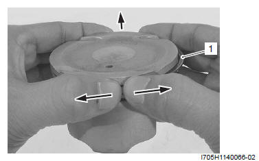
2) Carefully spread the ring opening with your thumbs and then push up the opposite side of the 1st ring (1) to remove it.
NOTE Do not expand the piston ring excessively since it is apt to be broken down.
3) Remove the 2nd ring and oil ring in the same procedures.
Installation
NOTE
- When installing the piston ring, be careful not to damage the piston.
- Do not expand the piston ring excessively since it is apt to be broken down.
1) Install the piston rings in the order of the oil ring, second ring and top ring.
a) The first member to go into the of the oil ring groove is a spacer (1).
After placing the spacer, fit the two side rails (2).
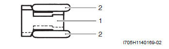
! CAUTION When installing the spacer, be careful so that the both edges are not overlapped.

- INCORRECT
- CORRECT
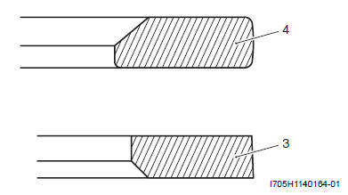
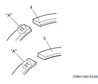
b) Install the 2nd ring (3) and 1st ring (4) to piston.
NOTE 1st ring (4) and 2nd ring (3) differ in shape.
NOTE Face the side with the stamped mark "A" upward when assembling.
2) Position the gaps of the three rings and side rails as shown. Before inserting piston into the cylinder, check that the gaps are so located.
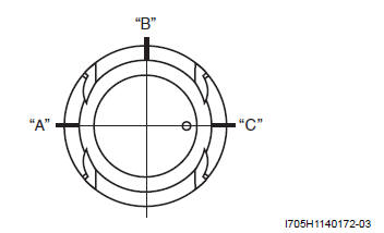
- 1st ring and upper side rail
- Spacer
- 2nd ring and lower side rail
3) Install the piston and piston pin. Refer to "Engine Top Side Assembly".
Piston and Related Parts Inspection
Refer to "Engine Top Side Disassembly ".
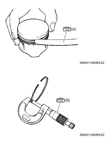
Piston Diameter
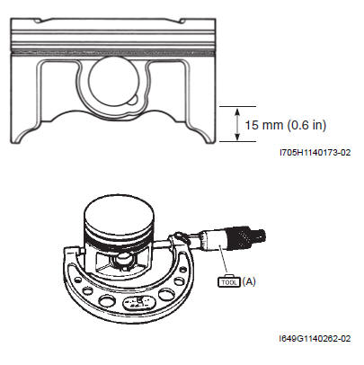
Measure the piston diameter using the micrometer at 15 mm (0.6 in) from the skirt end. If the piston diameter is less than the service limit, replace the piston.
Special tool (A): 09900-20204 (Micrometer (75 - 100 mm) )
Piston diameter
Service limit: 80.880 mm (3.1842 in)
Piston-to-Cylinder Clearance
Subtract the piston diameter from the cylinder bore diameter. If the piston-to-cylinder clearance exceeds the service limit, replace both the cylinder and the piston.
Piston-to-cylinder clearance
Service limit: 0.12 mm (0.0047 in)
Piston Ring-to-Groove Clearance
Measure the side clearances of the 1st and 2nd piston rings using the thickness gauge. If any of the clearances exceed the limit, replace both the piston and piston rings.
Special tool
(A): 09900-20803 (Thickness gauge)
(B): 09900-20205 (Micrometer (0 - 25 mm) )
Piston ring-to-groove clearance
Service limit: (1st): 0.18 mm (0.007 in)
Service limit: (2nd): 0.15 mm (0.006 in)
Piston ring groove width
Standard: (1st): 1.21 - 1.23 mm (0.0476 - 0.0484 in)
Standard: (2nd): 1.01 - 1.03 mm (0.0398 - 0.0406 in)
Standard: (Oil): 2.01 - 2.03 mm (0.0791 - 0.0799 in)
Piston ring thickness
Standard: (1st): 1.17 - 1.19 mm (0.0461 - 0.0469 in)
Standard: (2nd): 0.97 - 0.99 mm (0.0382 - 0.0396 in)
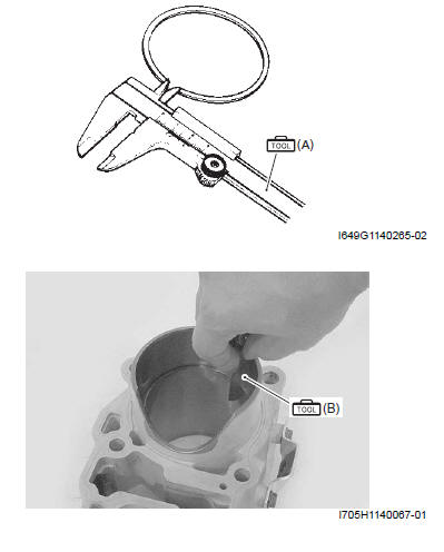
Piston Ring Free End Gap and Piston Ring End Gap
Measure the piston ring free end gap using vernier calipers. Next, fit the piston ring squarely into the cylinder and measure the piston ring end gap using the thickness gauge. If any of the measurements exceed the service limit, replace the piston ring with a new one.
Special tool (A): 09900-20102 (Vernier calipers)
Piston ring free end gap
Service limit: (1st): 6.0 mm (0.24 in)
Service limit: (2nd): 9.2 mm (0.36 in)
Special tool (B): 09900-20803 (Thickness gauge)
Piston ring end gap
Service limit: (1st): 0.5 mm (0.020 in)
Service limit: (2nd): 0.5 mm (0.020 in)
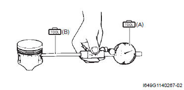
Piston Pin and Pin Bore
Measure the piston pin bore inside diameter using the small bore gauge. If either is out of specification or the difference between these measurement is more than the limits, replace the piston.
Special tool
(A): 09900-20602 (Dial gauge (1/1000 mm, 1 mm) )
(B): 09900-22403 (Small bore gauge (18 - 35 mm) )
Piston pin bore I.D.
Service limit: 20.030 mm (0.7886 in)
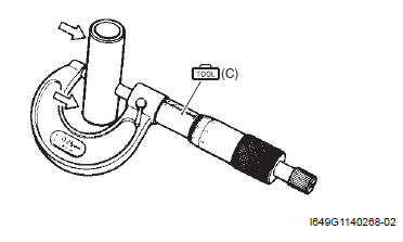
Measure the piston pin outside diameter at three positions using the micrometer. If any of the measurements are out of specification, replace the piston pin.
Special tool (C): 09900-20205 (Micrometer (0 - 25 mm) )
Piston pin O.D.
Service limit: 19.980 mm (0.7866 in)
See also:
 Suzuki Burgman 400 - Service manual > Cylinder Head Related Parts Inspection
Cylinder Head Distortion 1) Decarbonize the combustion chambers. 2) Check the gasket surface of the cylinder head for distortion. Use a straightedge and thickness gauge.
Suzuki Burgman 400 - Service manual > Engine Bottom Side
Engine Bottom Side Disassembly ! CAUTION Identify the position of each removed part. Organize the parts in their respective groups (e.g., intake, exhaust) so that they can be reinstalled in their original positions.


