 Suzuki Burgman 400 - Service manual > Engine Bottom Side
Engine Bottom Side Disassembly
! CAUTION Identify the position of each removed part.
Organize the parts in their respective groups (e.g., intake, exhaust) so that they can be reinstalled in their original positions.
NOTE The crankcase must be separated to service the crankshaft, oil pump.
1) Remove the engine assembly. Refer to "Engine Assembly Removal and Installation".
2) Remove the cylinder head, cylinder and piston.
Refer to "Engine Top Side Disassembly".
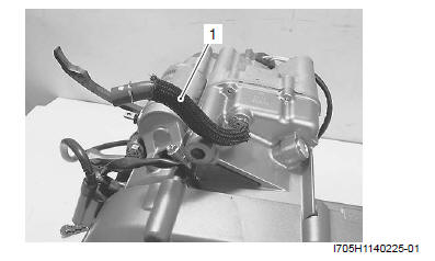
PCV hose
Remove the PCV hose (1).
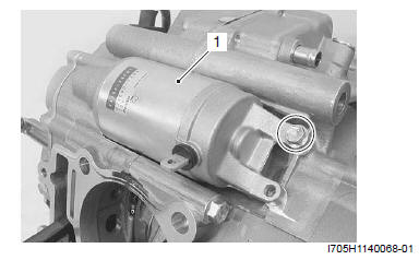
Starter Motor
Remove the starter motor (1).
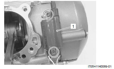
Ignition Coil
Remove the ignition coil (1).
Water Pump
Remove the water pump assembly (1).
Generator Cover
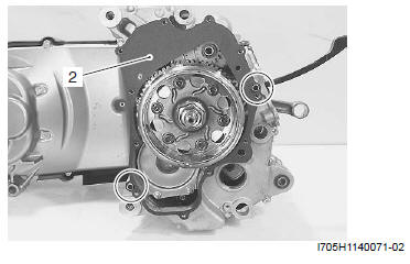
1) Remove the generator cover (1).
2) Remove the dowel pins and gasket (2).
Outer Clutch Cover
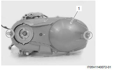
Remove the outer clutch cover (1).
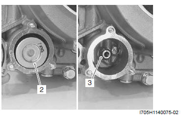
Oil Filter
1) Remove the oil filter cap (1).
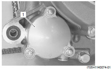
2) Remove the oil filter (2) and O-ring (3).
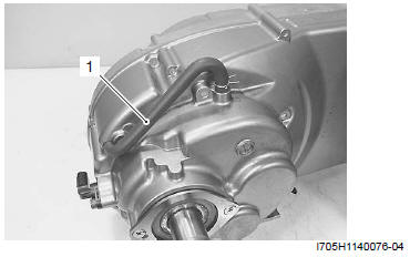
Transmission Breather Hose
Remove the transmission breather hose (1).
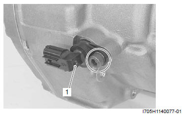
Speed Sensor
Remove the speed sensor (1).
Drivetrain
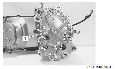
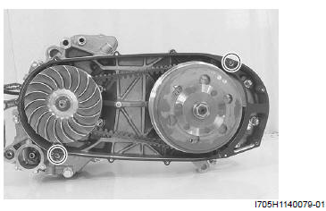
1) Remove the inner clutch cover (1).
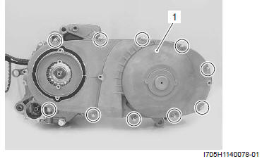
2) Remove the dowel pins and gasket.
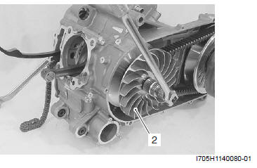
3) With the crankshaft held immovable, remove the fixed drive face nut and concaved washer.
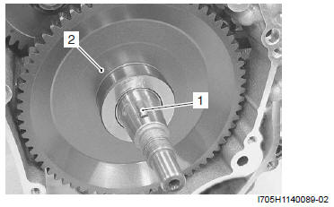
4) Remove the fixed drive face (2).
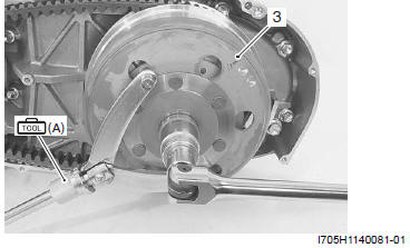
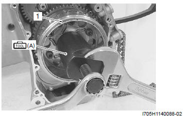
5) With the clutch housing held immovable using the special tool, remove the clutch housing nut and concaved washer.
6) Remove the clutch housing (3).
Special tool (A): 09930-40113 (Rotor holder)
7) Remove the drive V-belt (4) and clutch shoe/ movable driven face assembly (5).
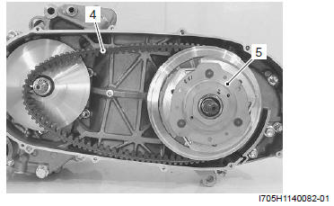
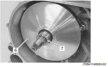
8) Remove the movable drive face assembly (6) with the spacer (7).
9) Remove the final gear assembly. Refer to "Final Gear Assembly Removal and Installation".
Generator Rotor
1) With the generator rotor held immovable, loosen the generator rotor nut.
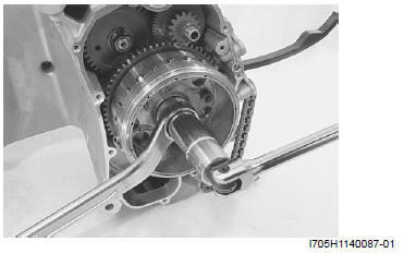
2) Remove the generator rotor (1) using the special tool.
Special tool (A): 09930-31921 (Rotor remover)
Starter Drive Gear
Remove the key (1) and starter driven gear (2).
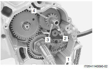
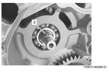
Cam Chain and Starter Idle Gear
1) Remove the cam chain (1), starter idle gear shaft (2), spacer (3) and starter idle gear (4).
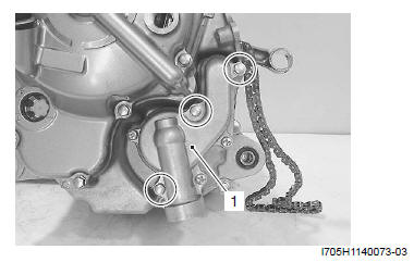
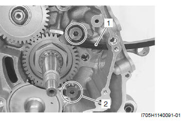
Cam Chain Tensioner
1) Remove the cam chain tensioner (1).
2) Remove the cam chain guide bolt (2).
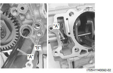
Balancer Driven Gear
1) Insert a proper steel rod "A" into the crankcase hole "B" and pass it through the crankshaft web holes in order to prevent the crankshaft from turning.
2) Remove the balancer driven gear nut (1) and washer.
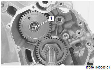
3) Remove the balancer driven gear (2) along with the scissors gear behind.
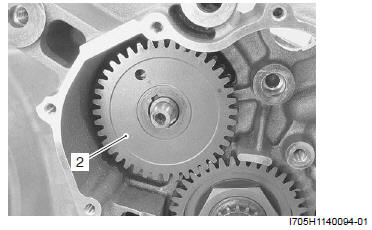
4) Remove the key (3).
See also:
 Suzuki Burgman 400 - Service manual > Valve Seat Repair
The valve seats (1) for both the intake and exhaust valves are machined to three different angles. The seat contact surface is cut at 45º.
Suzuki Burgman 400 - Service manual > Oil Pump Drive Gear
1) Remove the oil pump drive gear cover (1). 2) Remove the oil pump drive gear nut (2).


