 Suzuki Burgman 400 - Service manual > Oil Pump Drive Gear
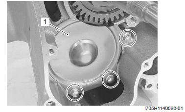
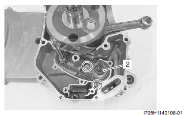
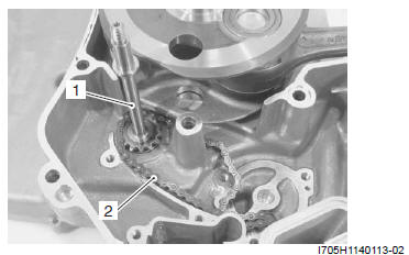
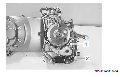
1) Remove the oil pump drive gear cover (1).
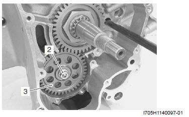
2) Remove the oil pump drive gear nut (2).
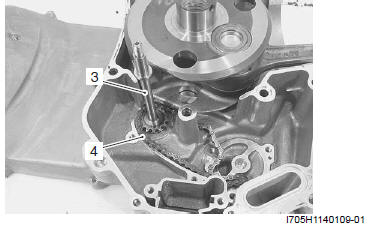
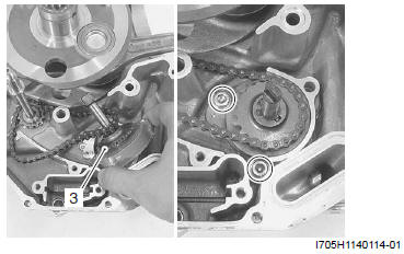
3) Remove the oil pump drive gear (3).
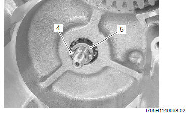
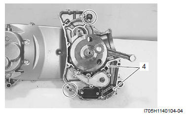
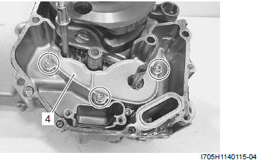
4) Remove the pin (4) and spacer (5).
Crankcase
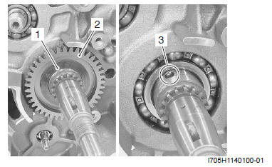
1) Remove the balancer drive gear nut.
Special tool (A): 09922-21410 (Long socket (46 mm) )
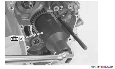
2) Remove the steel rod.
3) Remove the washer (1) and balancer drive gear (2).
4) Remove the pin (3).
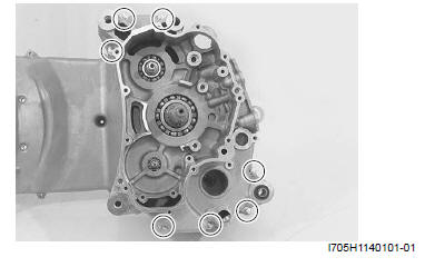
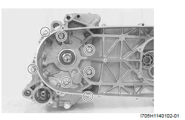
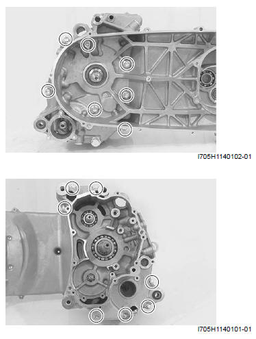
5) Remove the crankcase bolts (M6 and M8).
! CAUTION Loosen the smaller diameter crankcase bolts first and then larger ones diagonally and evenly.
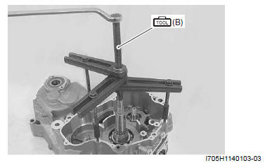
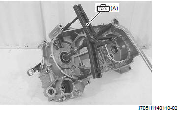
6) Separate the crankcase using the special tool.
Special tool (B): 09920-13120 (Crankcase separating tool)
NOTE
- Set the special tool so that the tool arms are in parallel with the end face of crankcase.
- The crankshaft should remain in the left crankcase half.
7) Remove the O-rings (4) and dowel pins.
Balancer Shaft
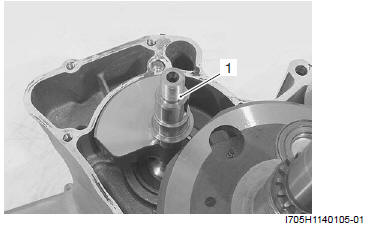
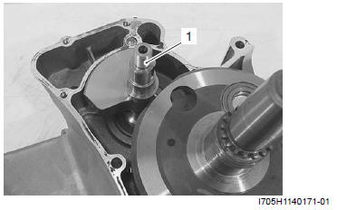
Remove the balancer shaft (1).
Oil Sump Filter
1) Remove the oil sump filter cover (1).
2) Remove the oil sump filter (2).
Oil Pump
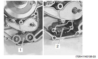
1) Remove the oil pump drive chain case (1).
2) Remove the oil pump assembly (2).
3) Remove the oil pump drive shaft (3) and chain (4).
Crankshaft
Remove the crankshaft using the spacial tool.
Special tool (A): 09920-13120 (Crankcase separating tool)
NOTE Set the special tool so that the tool arms are in parallel with the end face of crankcase.
Engine Bottom Side Assembly
Assemble the engine bottom side in the reverse of disassembly. Pay attention to the following points:
Crankshaft
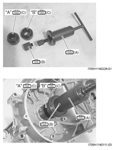
- Using the special tools, press in the crankshaft into the left crankcase.
NOTE When pressing in the crankshaft into the crankcase, insert the inner driver attachments "A" (φ25 mm) and "B" (φ30 mm) of the bearing installer set between the crankcase bearing inner lace and crankshaft installer.
Special tool
(A): 09910-32812 (Crankshaft installer)
(B): 09910-32870 (Crankshaft installer attachment)
(C): 09913-70210 (Bearing installer set)
! CAUTION
- Do not hit the crankshaft with a plastic hammer or the like to install the crankshaft into the crankcase.
- Make sure that the direction of conrod is turned toward the cylinder hole.
Oil Pump
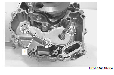
- Install the oil pump drive shaft (1) and oil pump drive chain (2) to the bearing.
- Install the oil pump assembly (3) and tighten the oil pump mounting bolt to the specified torque.
Tightening torque
Oil pump mounting bolt: 10 N*m (1.0 kgf-m, 7.0 lb-ft)
- Install the oil pump drive chain cover (4).
Oil Sump Filter
Refer to "Oil Sump Filter Removal and Installation".
Balancer Shaft
- Install the balancer shaft (1).
NOTE Bring the straightened part of the crank web toward the balancer shaft.
Crankcase
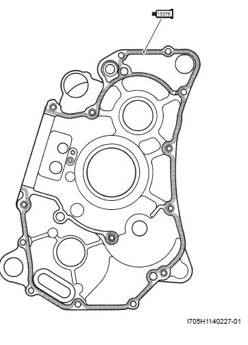
- Install the O-rings (1) and (2).
- Install the dowel pins.
! CAUTION Replace the O-rings with the new ones.
- Clean and degrees the crankcase mating surfaces (both surfaces) with a cleaning solvent.
- Apply bond to the right crankcase.
 : Sealant
99000-31140 (SUZUKI BOND No.1207B or equivalent)
: Sealant
99000-31140 (SUZUKI BOND No.1207B or equivalent)
! CAUTION
- Coat the sealant evenly without break.
- Application of sealant must be performed within a short period of time.
- Take extreme care not to let sealant enter into the oil passages or bearings.
- Tighten the crankcase bolts to the specified torque.
Tightening torque
Crankcase bolt (M6): 11 N*m (1.1 kgf-m, 8.0 lb-ft)
Crankcase bolt (M8): 22 N*m (2.2 kgf-m, 16.0 lb-ft)
! CAUTION Tighten the larger diameter crankcase bolts first and then smaller ones diagonally and evenly.
NOTE After crankcase bolts have been tightened, check it crankshaft rotate smoothly.
See also:
 Suzuki Burgman 400 - Service manual > Engine Bottom Side
Engine Bottom Side Disassembly ! CAUTION Identify the position of each removed part. Organize the parts in their respective groups (e.g., intake, exhaust) so that they can be reinstalled in their original positions.
Suzuki Burgman 400 - Service manual > Balancer Drive Gear
Insert the pin (1). Install the balancer drive gear (2) and washer (3). ! CAUTION Make sure to align the slot of the balancer drive gear with the pin. Set the washer with its convex side facing outside. Insert a proper steel rod "A" into the crankcase hole and pass it through the crankshaft wed holes in order to prevent the crankshaft from turning. Using the special tool, tighten the balancer drive gear nut to the specified torque.


