 Suzuki Burgman 400 - Service manual > Diagnostic Information and Procedures
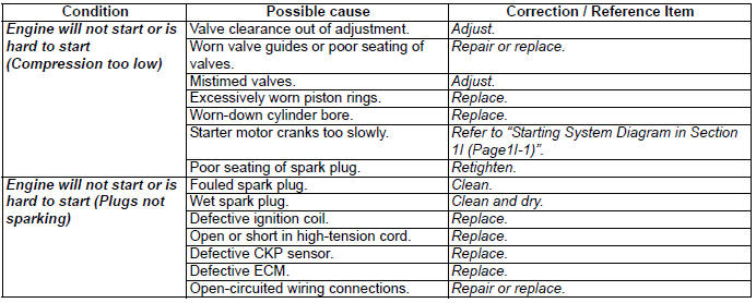
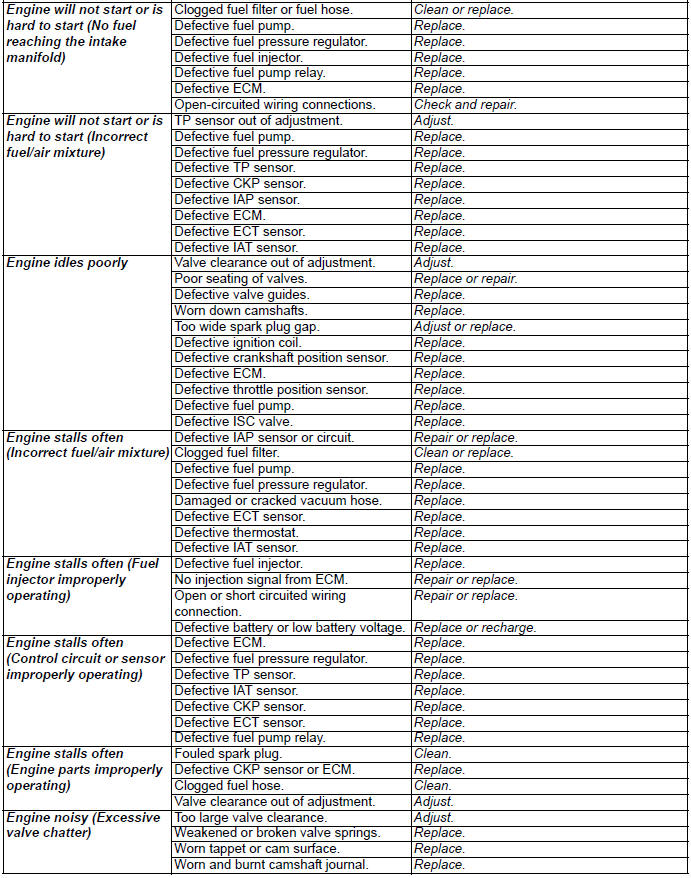
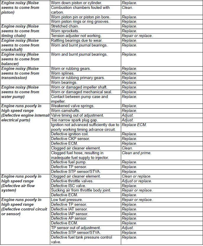
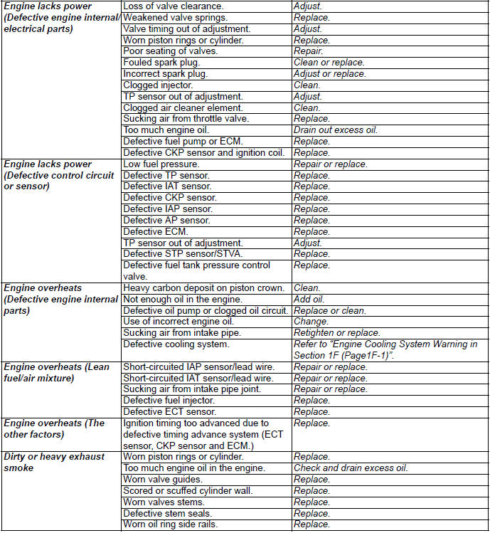
Engine Symptom Diagnosis
DTC Table
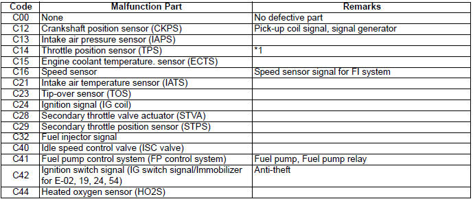
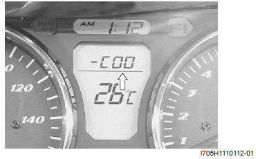
In the LCD (DISPLAY) panel, the malfunction code is indicated from small code to large code.
*1 To get the proper signal from the throttle position sensor, the sensor basic position is indicated in the LCD (DISPLAY) panel. The malfunction code is indicated in three digits. In front of the three digits, a line appears in any of the three positions, upper, middle or lower line. If the indication is upper or lower line when engine rpm is 1 450 r/min, slightly turn the throttle position sensor and bring the line to the middle.
Fail-Safe Function Table
FI system is provided with fail-safe function to allow the engine to start and the motorcycle to run in a minimum performance necessary even under malfunction condition.
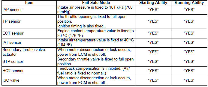
The engine can start and can run even if the signal in the table is not received from each sensor. But, the engine running condition is not complete, providing only emergency help (by fail-safe circuit). In this case, it is necessary to bring the motorcycle to the workshop for complete repair.
FI System Troubleshooting
Customer Complaint Analysis
Record details of the problem (failure, complaint) and how it occurred as described by the customer. For this purpose, use of such an inspection form will facilitate collecting information to the point required for proper analysis and diagnosis.
EXAMPLE: CUSTOMER PROBLEM INSPECTION FORM
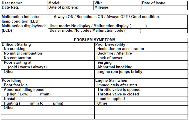
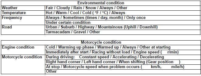
MOTORCYCLE/ENVIRONMENTAL CONDITION WHEN PROBLEM OCCURS
NOTE This form is a standard sample. The form should be modified according to conditions and characteristic of each market.
Visual Inspection
Prior to diagnosis using the mode select switch or SDS, perform the following visual inspections. The reason for visual inspection is that mechanical failures (such as oil leakage) cannot be displayed on the screen with the use of mode select switch or SDS.
- Engine oil level and leakage.
- Engine coolant level and leakage.
- Fuel level and leakage.
- Clogged air cleaner element.
- Battery condition.
- Throttle cable play.
- Broken fuse.
- FI light operation.
- Each warning light operation.
- Speedometer operation.
- Exhaust gas leakage and noise.
- Each coupler disconnection.
Self-Diagnostic Procedures
NOTE
- Do not disconnect coupler from ECM, battery cable from battery, ECM ground wire harness from engine or main fuse before confirming DTC (Diagnostic Trouble Code) stored in memory. Such disconnection will erase memorized information in ECM memory.
- DTC stored in ECM memory can be checked by the special tool.
- Before checking DTC, read SELF-DIAGNOSIS FUNCTION "USER MODE and DEALER MODE" (Refer to "Self-Diagnosis Function \) carefully to have good understanding as to what functions are available and how to use it.
- Be sure to read "PRECAUTIONS for Electrical Circuit Service" (Refer to "Precautions for Electrical Circuit Service) before inspection and observe what is written there.
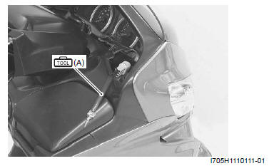
1) Remove the upper meter panel. Refer to "Upper Meter Panel Removal and Installation".
2) Connect the special tool to the dealer mode coupler (A) at the wiring harness, and start the engine or crank the engine for more than 4 seconds.
Special tool (A): 09930-82720 (Mode select switch)
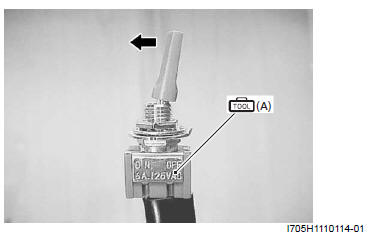
3) Turn the special tool's switch ON and check the malfunction code to determine the malfunction part.
Special tool (A): 09930-82720 (Mode select switch)
Self-Diagnosis Reset Procedures
1) After repairing the trouble, turn OFF the ignition switch and turn ON again. If DTC is indicated (C00), the malfunction is cleared.
2) Disconnect the special tool from the dealer mode coupler.
NOTE
- Even though DTC (C00) is indicated, the previous history DTC still remains stored in the ECM. Therefore, erase the history DTC memorized in the ECM using SDS.
- DTC is memorized in the ECM also when the wire coupler of any sensor is disconnected. Therefor, when a wire coupler has been disconnected at the time of diagnosis, erase the stored history DTC using SDS.
Use of SDS Diagnostic Procedures
NOTE
- Do not disconnect the coupler from ECM, the battery cable from the battery, ECM ground wire harness from the engine or main fuse before confirming DTC (Diagnostic Trouble Code) stored in memory. Such disconnection will erase the memorized information in ECM memory.
- DTC stored in ECM memory can be checked by the SDS.
- Be sure to read "Precautions for Electrical Circuit Service" before inspection and observe what is written there.
1) Remove the upper meter panel. Refer to "Upper Meter Panel Removal and Installation".
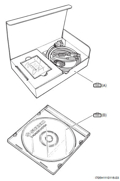
2) Set up the SDS tools. (Refer to the SDS operation manual for further details.)
Special tool
(A): 09904-41010 (SDS Set)
(B): 99565-01010-008 (CD-ROM Ver.8)
3) Read the DTC (Diagnostic Trouble Code) and show data when trouble (displaying data at the time of DTC) according to instructions displayed on SDS.
SDS is not only used for detecting Diagnostic.
4) Trouble Codes but also for reproducing and checking on screen the failure condition as described by customers using the trigger.
5) Refer to the SDS operation manual for How to use trigger and further details.
Use of SDS Diagnosis Reset Procedures
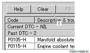
Clear the Past DTC using SDS in the following procedures:
1) Set up the SDS tools.
2) After repairing the trouble, turn OFF the ignition switch and turn ON again.
3) Click the DTC inspection button (1).
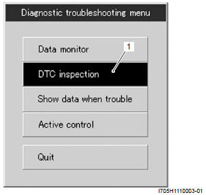
4) Check the DTC.
5) The previous malfunction history code (Past DTC) still remains stored in the ECM. Therefore, erase the history code memorized in the ECM using SDS tool.
NOTE The malfunction code is memorized in the ECM also when the wire coupler of any sensor is disconnected. Therefore, when a wire coupler has been disconnected at the time of diagnosis, erase the stored malfunction history code using SDS.
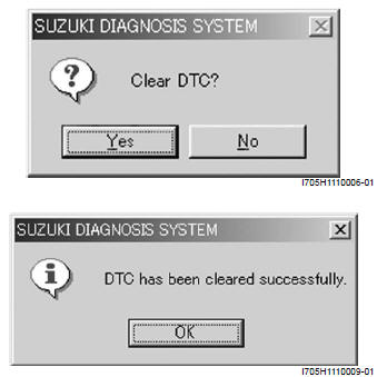
6) Click "Clear" (2) to delete history code (Past DTC).
7) Follow the displayed instructions.
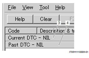
8) Check that both "Current DTC" (3) and "Past DTC" (4) are deleted (NIL).
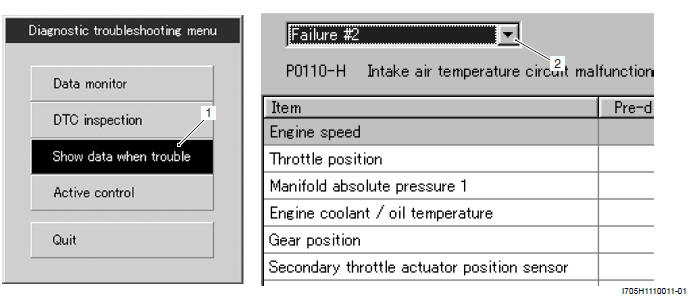
Show Data When Trouble (Displaying Data at the Time of DTC)
ECM stores the engine and driving conditions (in the form of data as shown in the figure) at the moment of the detection of a malfunction in its memory. This data is called "Show data when trouble".
Therefore, it is possible to know engine and driving conditions (e.g., whether the engine was warm or not, where the motorcycle was running or stopped) when a malfunction was detected by checking the show data when trouble. This show data when trouble function can record the maximum of two Diagnostic Trouble Codes in the ECM.
Also, ECM has a function to store each show data when trouble for two different malfunctions in the order as the malfunction is detected. Utilizing this function, it is possible to know the order of malfunctions that have been detected.
Its use is helpful when rechecking or diagnosing a trouble.
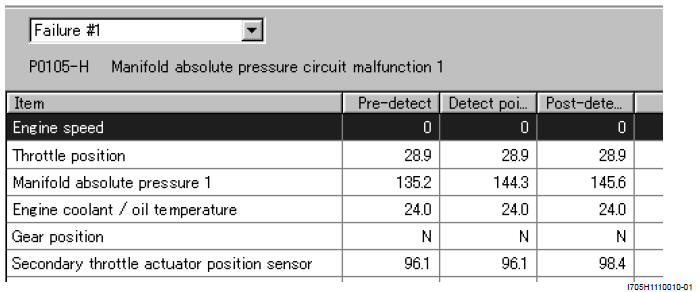
Click "Show data when trouble" (1) to display the data. By clicking the drop down button (2), either "Failure #1" or "Failure #2" can be selected.
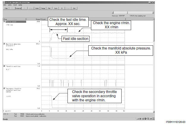
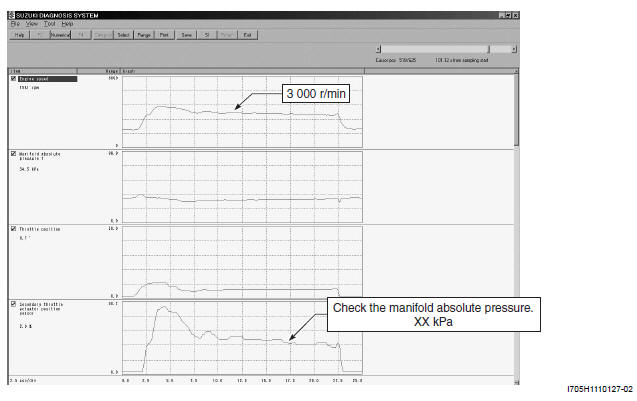
SDS Check
Using SDS, take the sample of data from the new motorcycle and at the time of periodic maintenance at your dealership.
Save the data in the computer or by printing and filing the hard copies. The saved of filed data are useful for troubleshooting as they can be compared periodically with changes over time or failure conditions of the motorcycle.
For example, when a motorcycle is brought in for service but the troubleshooting is difficult, comparison with the normal data that have been saved or filed can allow the specific engine failure to be determined.
- Remove the upper meter panel. Refer to "Upper Meter Panel Removal and Installation".
- Set up the SDS tool. Refer to "Use of SDS Diagnostic Procedures".
Special tool
: 09904-41010 (SDS set)
: 99565-01010-008 (CD-ROM Ver.8)
NOTE
- Before taking the sample of data, check and clear the Past DTC.
- A number of different data under a fixed condition as shown below should be saved or filed as sample.
Sample
Data sampled from cold starting through warm-up
Data at 3 000 r/min under no load
Data at the time of racing
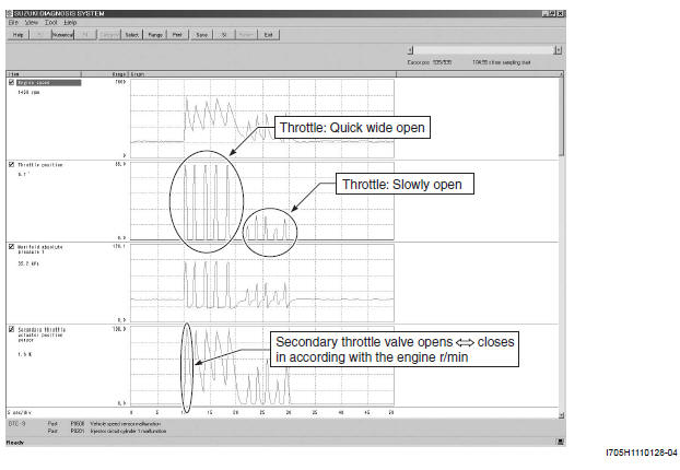
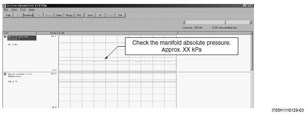
Data of intake negative pressure during idling (100 ºC)
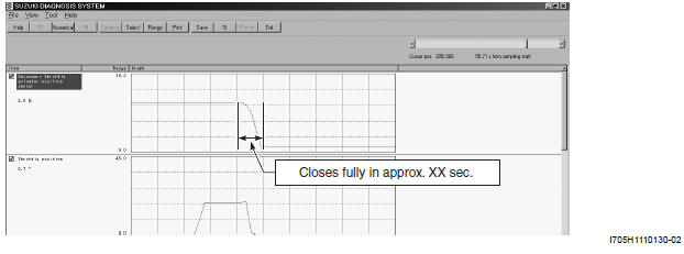
Data of secondary throttle valve operation at the time of starting
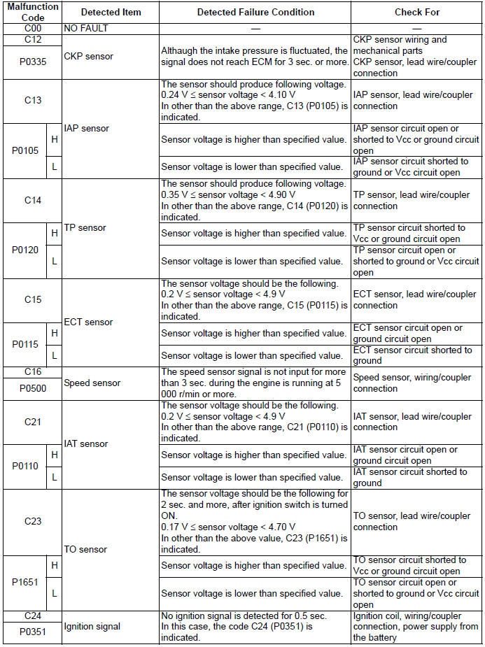
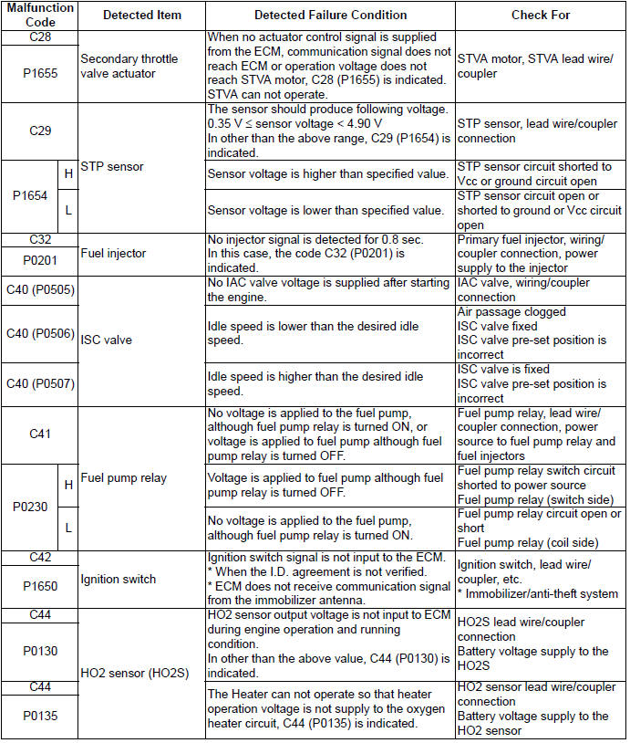
Malfunction Code and Defective Condition Table
* : Immobilizer system is equipped model only.
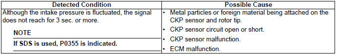
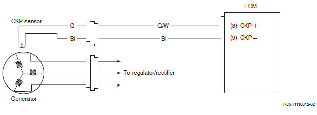
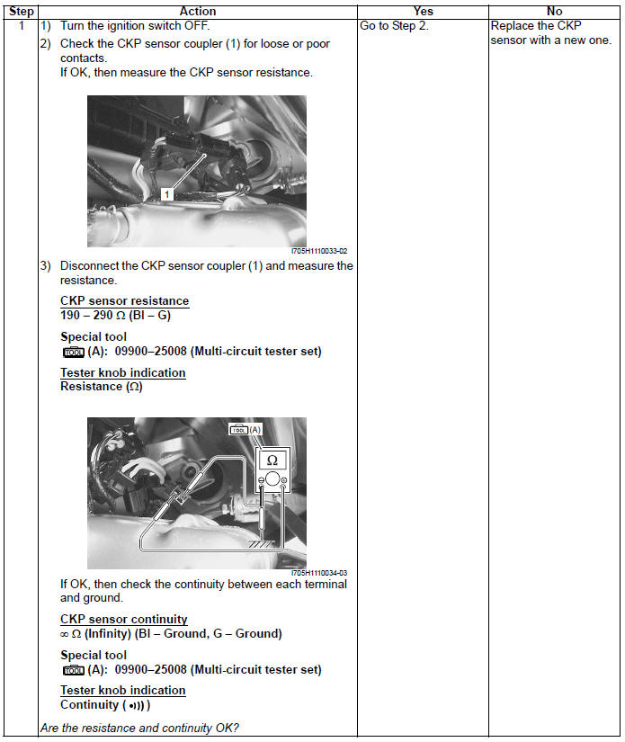
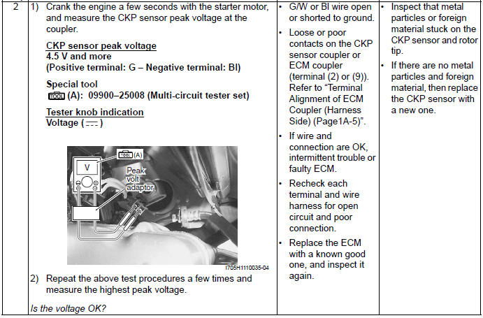
DTC "C12" (P0335): CKP Sensor Circuit Malfunction
Detected Condition and Possible Cause
Wiring Diagram
Troubleshooting
NOTE After repairing the trouble, clear the DTC using SDS tool. Refer to "Use of SDS Diagnosis Reset Procedures".
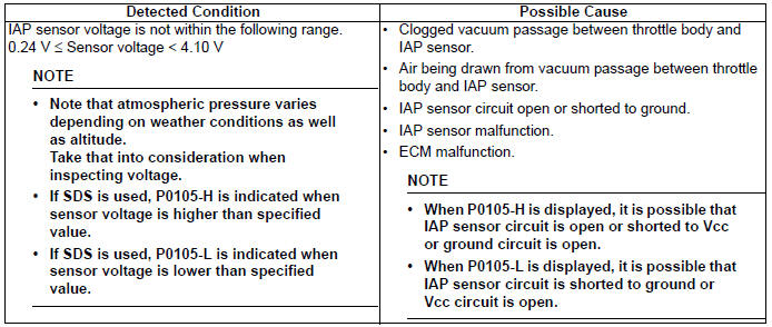
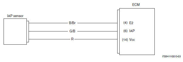
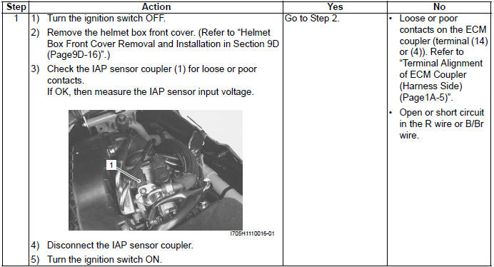
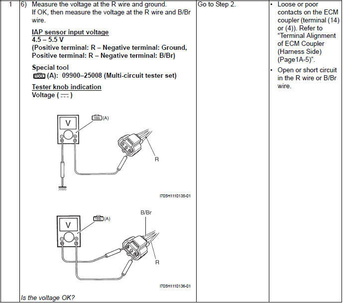
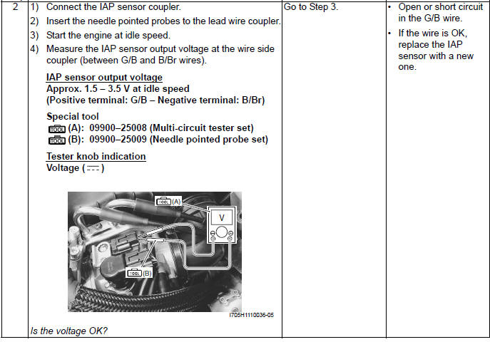
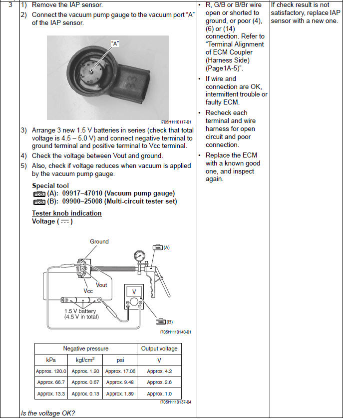
DTC "C13" (P0105-H/L): IAP Sensor Circuit Malfunction
Detected Condition and Possible Cause
Wiring Diagram
Troubleshooting
! CAUTION When using the multi-circuit tester, do not strongly touch the terminal of the ECM coupler with a needle pointed tester probe to prevent the terminal damage or terminal bend.
NOTE After repairing the trouble, clear the DTC using SDS tool. Refer to "Use of SDS Diagnosis Reset Procedures ".
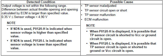
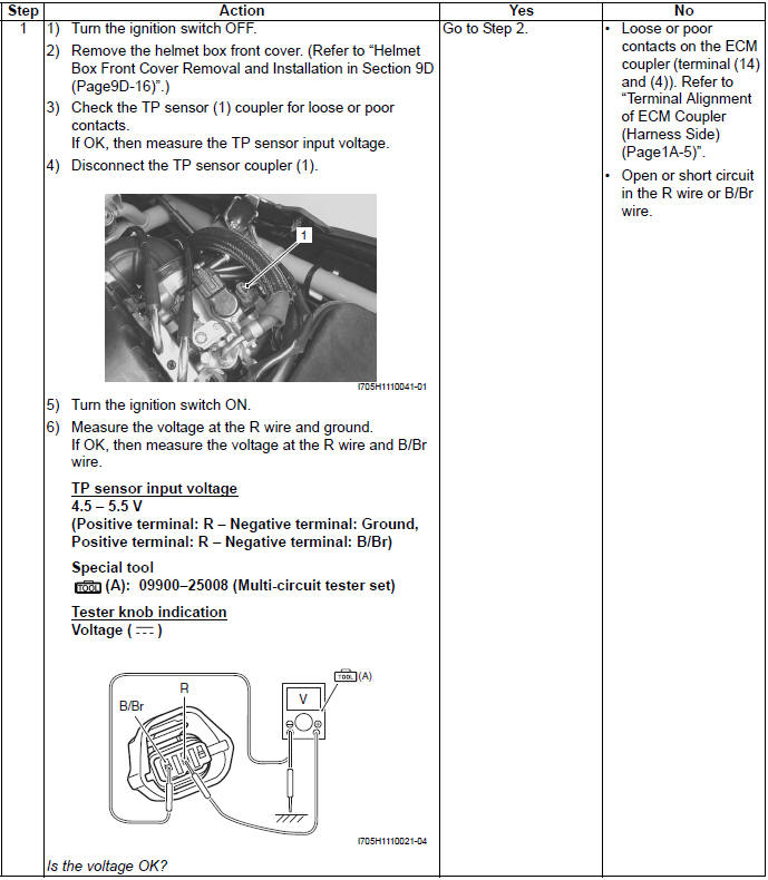
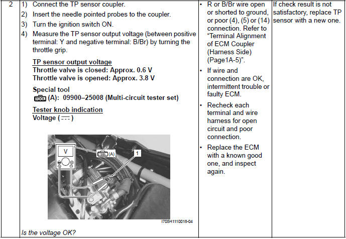
DTC "C14" (P0120/H/L): TP Sensor Circuit Malfunction
Detected Condition and Possible Cause
Wiring Diagram
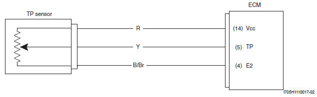
Troubleshooting
! CAUTION When using the multi-circuit tester, do not strongly touch the terminal of the ECM coupler with a needle pointed tester probe to prevent the terminal damage or terminal bend.
NOTE After repairing the trouble, clear the DTC using SDS tool. Refer to "Use of SDS Diagnosis Reset Procedures ".
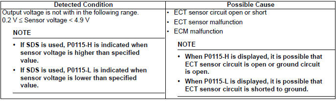
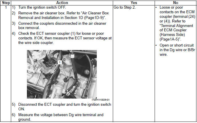
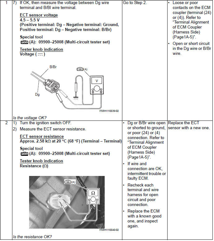
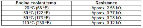
DTC "C15" (P0115-H/L): ECT Sensor Circuit Malfunction
Detected Condition and Possible Cause
Wiring Diagram
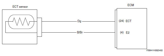
Troubleshooting
! CAUTION When using the multi-circuit tester, do not strongly touch the terminal of the ECM coupler with a needle pointed tester probe to prevent the terminal damage or terminal bend.
NOTE
- After repairing the trouble, clear the DTC using SDS tool. Refer to "Use of SDS Diagnosis Reset Procedures".
- Refer to "ECT Sensor Inspection".
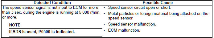
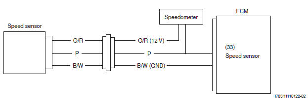
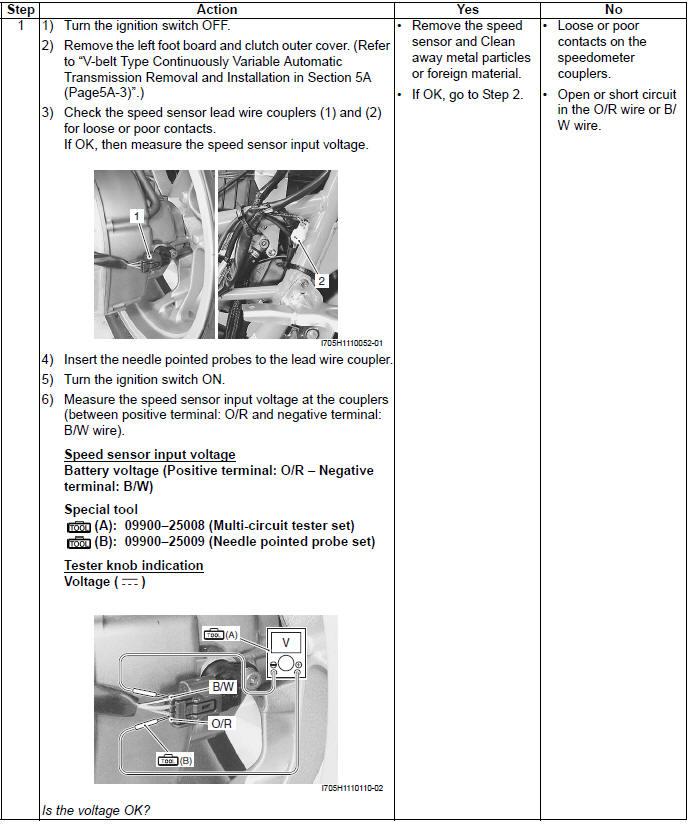
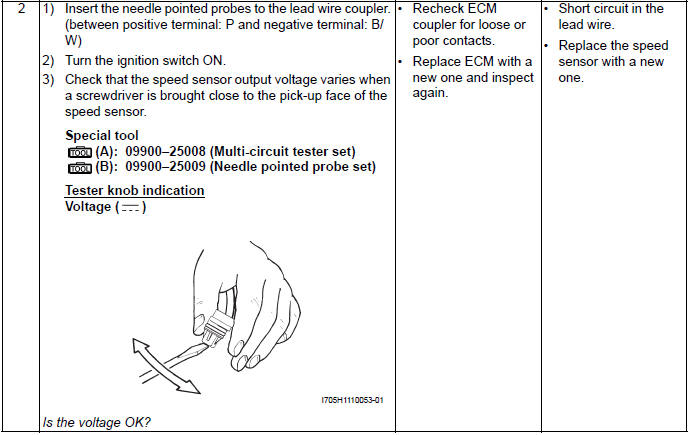
DTC "C16" (P0500): Speed Sensor
Detected Condition and Possible Cause
Wiring Diagram
Troubleshooting
! CAUTION When using the multi-circuit tester, do not strongly touch the terminal of the ECM coupler with a needle pointed tester probe to prevent the terminal damage or terminal bend.
NOTE
- After repairing the trouble, clear the DTC using SDS tool. Refer to "Use of SDS Diagnosis Reset Procedures".
- Refer to "Use of SDS Diagnosis Reset Procedures"
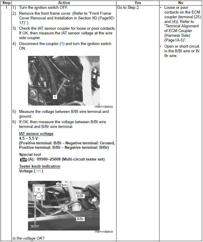
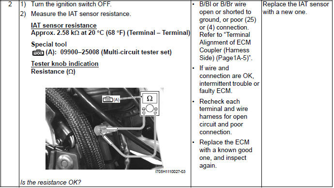
DTC "C21" (P0110-H/L): IAT Sensor Circuit Malfunction
Detected Condition and Possible Cause

Wiring Diagram
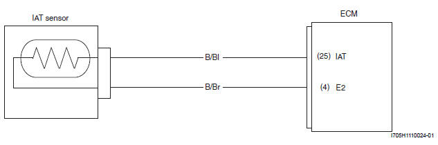
Troubleshooting
! CAUTION When using the multi-circuit tester, do not strongly touch the terminal of the ECM coupler with a needle pointed tester probe to prevent the terminal damage or terminal bend.
NOTE
- After repairing the trouble, clear the DTC using SDS tool. Refer to "Use of SDS Diagnosis Reset Procedures ".
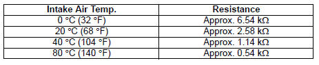
- IAT sensor resistance measurement method is the same way as that of the ECT sensor. Refer to "IAT Sensor Inspection" for details.
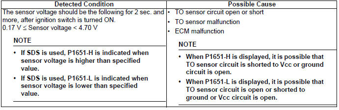
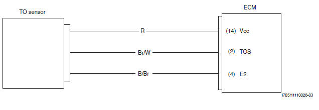
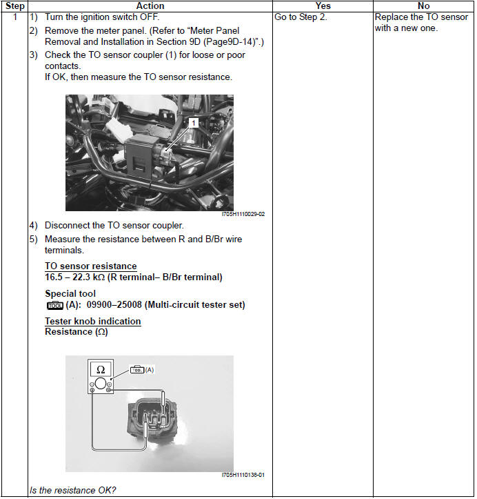
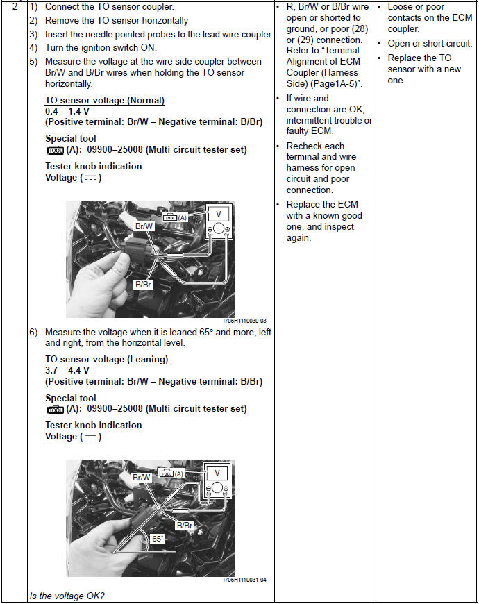
DTC "C23" (P1651-H/L): TO Sensor Circuit Malfunction
Detected Condition and Possible Cause
Wiring Diagram
Troubleshooting
! CAUTION When using the multi-circuit tester, do not strongly touch the terminal of the ECM coupler with a needle pointed tester probe to prevent the terminal damage or terminal bend.
NOTE After repairing the trouble, clear the DTC using SDS tool. Refer to "Use of SDS Diagnosis Reset Procedures".
DTC "C24" (P0351): Ignition System Malfunction
Refer to "No Spark or Poor Spark" for details.
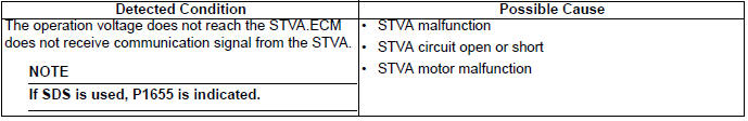
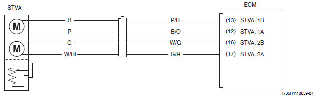
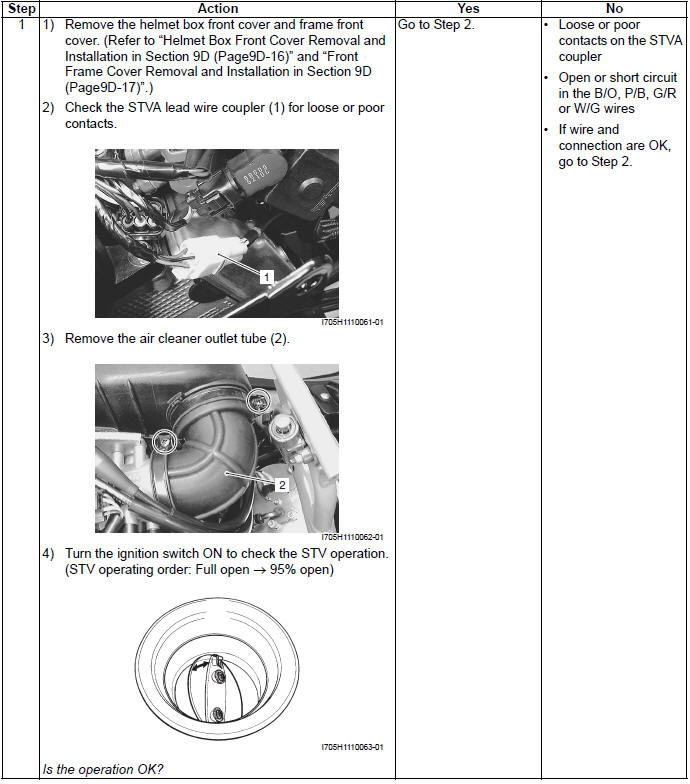
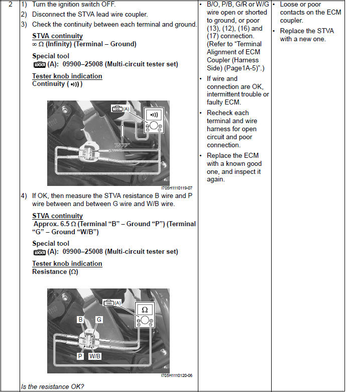
DTC "C28" (P1655): Secondary Throttle Valve Actuator (STVA) Malfunction
Detected Condition and Possible Cause
Wiring Diagram
Troubleshooting
! CAUTION When using the multi-circuit tester, do not strongly touch the terminal of the ECM coupler with a needle pointed tester probe to prevent the terminal damage or terminal bend.
NOTE After repairing the trouble, clear the DTC using SDS tool. Refer to "Use of SDS Diagnosis Reset Procedures".
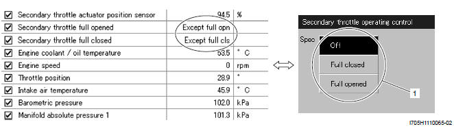
Active Control Inspection
1) Set up the SDS tool. (Refer to the SDS operation manual for further details.)
2) Turn the ignition switch ON.
3) Click "Secondary throttle operating control".
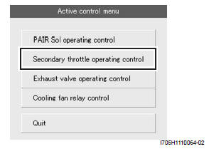
4) Click each button (1).
At this time, if an operation sound is heard from the STVA, the function is normal.
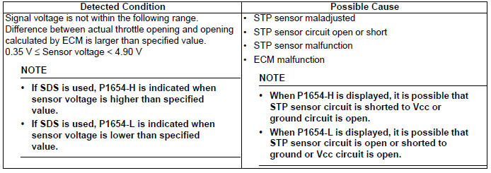
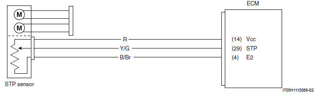
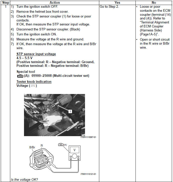
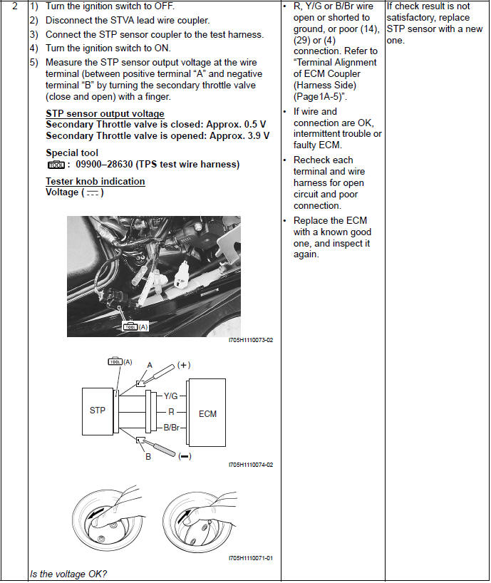
DTC "C29" (P1654-H/L): Secondary Throttle Position Sensor (STPS)
Detected Condition and Possible Cause
Wiring Diagram
Troubleshooting
! CAUTION When using the multi-circuit tester, do not strongly touch the terminal of the ECM coupler with a needle pointed tester probe to prevent the terminal damage or terminal bend.
NOTE After repairing the trouble, clear the DTC using SDS tool. Refer to "Use of SDS Diagnosis Reset Procedures ".
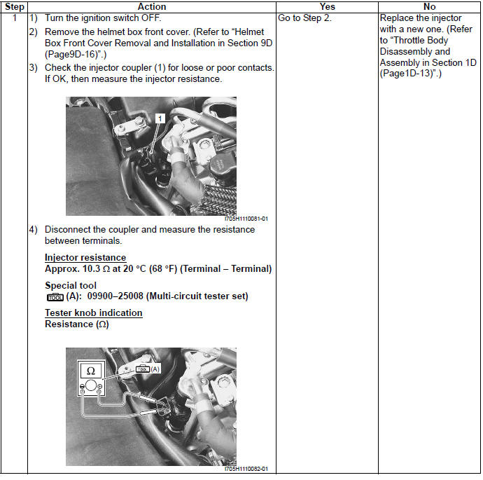
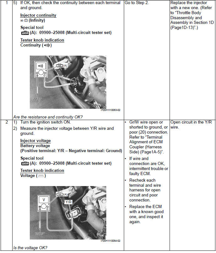
DTC "C32" (P0201): Fuel Injector Circuit Malfunction
Detected Condition and Possible Cause
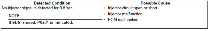
Wiring Diagram
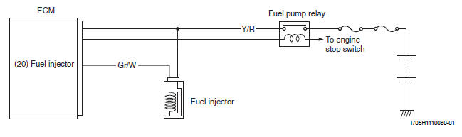
Troubleshooting
! CAUTION When using the multi-circuit tester, do not strongly touch the terminal of the ECM coupler with a needle pointed tester probe to prevent the terminal damage or terminal bend.
NOTE
- After repairing the trouble, clear the DTC using SDS tool. Refer to "Use of SDS Diagnosis Reset Procedures ".
- Injector voltage can be detected only for 3 seconds after ignition switch ON.
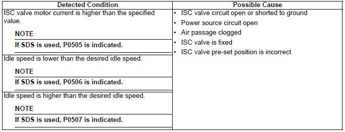
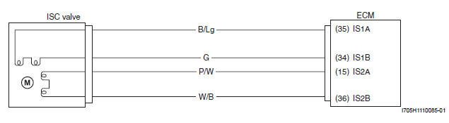
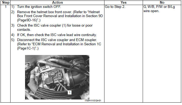
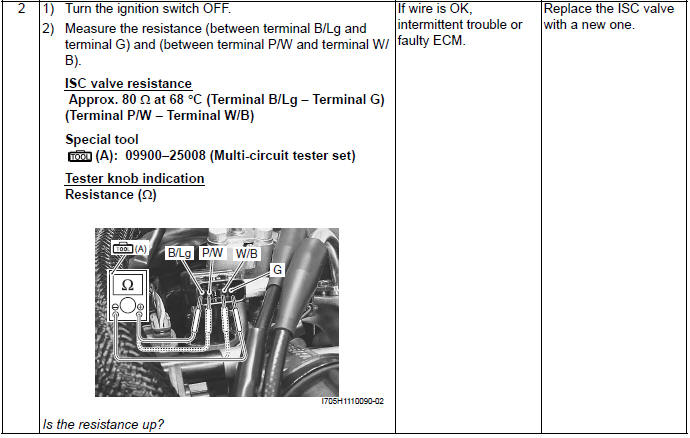
DTC "C40" (P0505, P0506 or P0507): ISC Valve Circuit Malfunction
Detected Condition and Possible Cause
Wiring Diagram
Troubleshooting
! CAUTION
- Be careful not to disconnect the ISC valve coupler at least 3
seconds after ignition switch is turned to OFF.
If the ECM coupler is disconnected within 3 seconds after ignition switch is turned to OFF, there is a possibility of an usual valve being written in ECM and causing an error of ISC valve operation.
- When using the multi-circuit tester, do not strongly touch the terminal of the ECM coupler with a needle pointed tester probe to prevent the terminal damage or terminal bend.
NOTE After repairing the trouble, clear the DTC using SDS tool. Refer to "Use of SDS Diagnosis Reset Procedures ".
ACTIVE CONTROL INSPECTION (ISC RPM CONTROL)
Check 1
1) Set up the SDS tool. (Refer to the SDS operation manual for further details.)
2) Check that the engine is running.
3) Click the "Active control".
4) Click the "ISC rpm control".
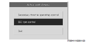
5) Check that the "Spec" (1) is idle speed 1 450 +- 100 rpm.
6) Check that the "Desired idle speed" (2) is within the specified idle rpm.
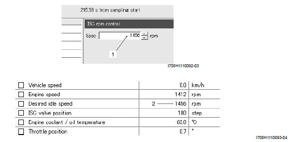
Check 2
1) Click the button (3) and decrease the "Spec" (1) to 1 200 rpm slowly.
2) Check that the "Desired idle speed" (2) is nearly equal to the "Spec" (1). At the same time, check that the number of steps (4) in the ISC valve position decreases.
3) Click the button (5) and increase the "Spec" (1) slowly.
4) Check that the "Desired idle speed" (2) is nearly equal to the "Spec" (1). Also, check that the number of steps (4) in the ISC valve position increases.
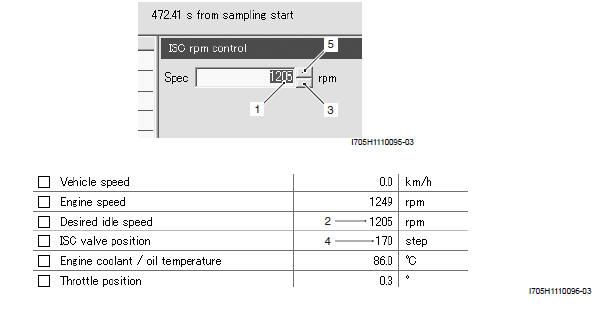
Check 3
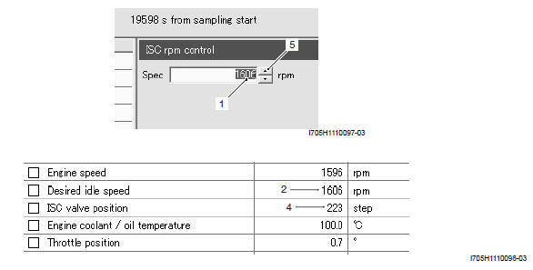
1) Click the button (5) and increase the "Spec" (1) to 1 600 rpm slowly.
2) Check that the "Desired idle speed" (2) is nearly equal to the "Spec" (1). Also, check that the number of steps (4) in the ISC valve position increases.
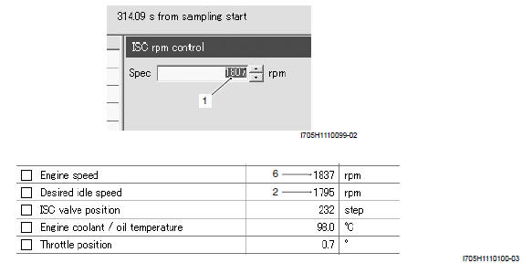
Check 4
1) Increase the "Spec" (1) to 1 795 rpm.
2) Check that the "Desired idle speed" (2) is approx. 1 795 rpm.
3) Check that the "Engine speed" (6) is close to 1 795 rpm.
NOTE Be careful not to increase the "Spec" to 1 800 rpm, or the "Engine speed" may reach the upper limit.
If the ISC valve does not function properly, replace the ISC valve or inspect the ISC valve. (Refer to "Throttle Body Disassembly and Assembly").
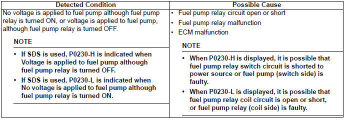
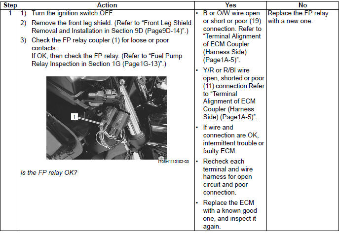
DTC "C41" (P0230-H/L): FP Relay Circuit Malfunction
Detected Condition and Possible Cause
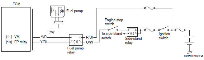
Wiring Diagram
Troubleshooting
! CAUTION When using the multi-circuit tester, do not strongly touch the terminal of the ECM coupler with a needle pointed tester probe to prevent the terminal damage or terminal bend.
NOTE After repairing the trouble, clear the DTC using SDS tool. Refer to "Use of SDS Diagnosis Reset Procedures ".
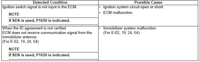
DTC "42" (P1650): IG Switch Circuit Malfunction
Detected Condition and Possible Cause
Troubleshooting
Refer to "Ignition Switch Inspection" for details.
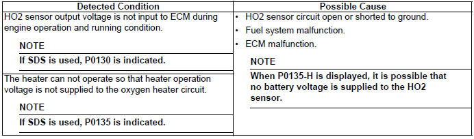
DTC "C44" (P0130, P0135): HO2 Sensor (HO2S) Circuit Malfunction
Detected Condition and Possible Cause
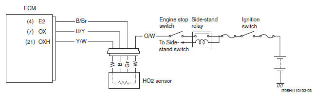
Wiring Diagram
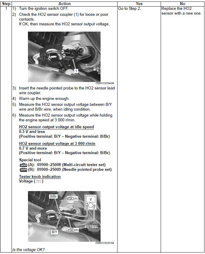
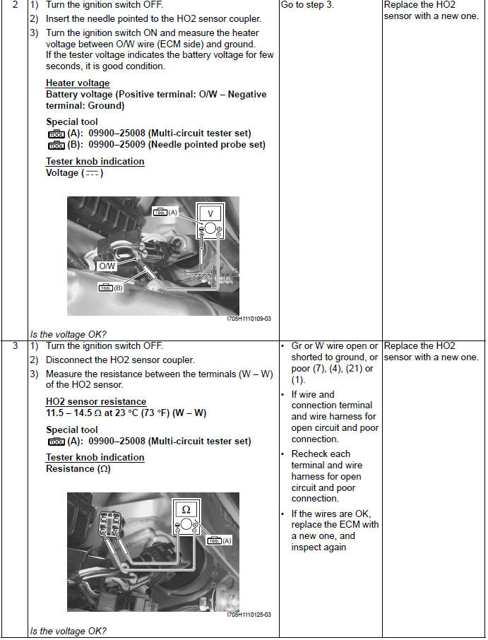
Troubleshooting
! CAUTION When using the multi-circuit tester, do not strongly touch the terminal of the ECM coupler with a needle pointed tester probe to prevent the terminal damage or terminal bend.
NOTE
- Battery voltage can be detected only during a few seconds after ignition switch is turned ON.
- Temperature of the sensor affects resistance value largely.
- Make sure that the sensor heater is at correct temperature.
- After repairing the trouble, clear the DTC using SDS tool. Refer to "Use of SDS Diagnosis Reset Procedures".
Specifications
Service Data
Injector

FI Sensors
Special Tools and Equipment
Special Tool
 09900-25008
Multi-circuit tester set
09900-25008
Multi-circuit tester set
 09900-25009
Needle pointed probe set
09900-25009
Needle pointed probe set
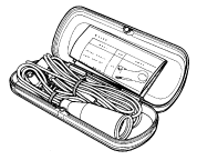
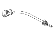
 09900-28630
TPS test wire harness
09900-28630
TPS test wire harness
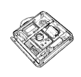
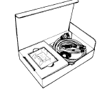 09904-41010
SDS set
09904-41010
SDS set
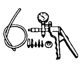 09917-47010
Vacuum pump gauge
09917-47010
Vacuum pump gauge
 09930-82720
Mode select switch
09930-82720
Mode select switch
 99565-01010-008
CD-ROM Ver.8
99565-01010-008
CD-ROM Ver.8
See also:
 Suzuki Burgman 400 - Service manual > Schematic and Routing Diagram
FI System Wiring Diagram Crankshaft position sensor (CKPS) Throttle position sensor (TPS) Intake air pressure sensor (IAPS) Secondary throttle position sensor (STPS) Engine coolant temperature sensor (ECTS) Intake air temperature sensor (IATS) Tip-over sensor (TOS) HO2 sensor Fuel injector Fuel pump (FP) Fuel pump relay (FP relay) Ignition coil Speed sensor Idle speed control valve (ISC valve) Secondary throttle valve actuator (STVA) Engine stop switch Side-stand relay Ignition switch Starter button Brake light switch Brake relay Side-stand switch Starter relay Starter motor Battery SDS


