 Suzuki Burgman 400 - Service manual > Schematic and Routing Diagram
FI System Wiring Diagram
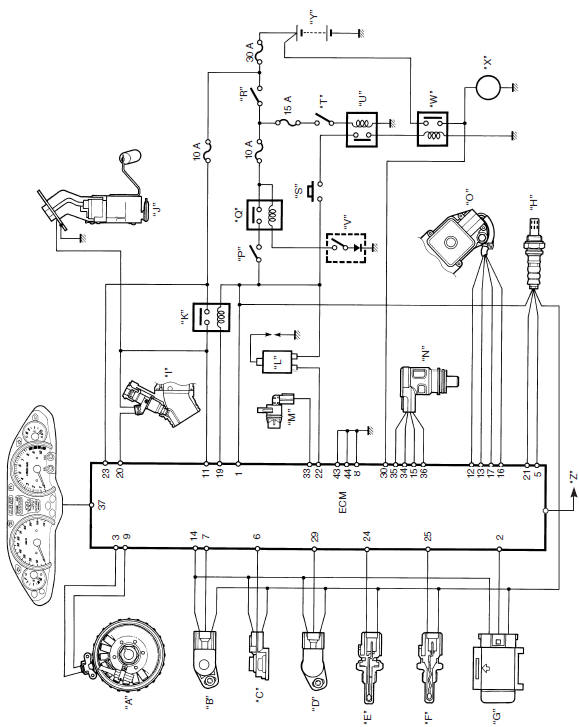
- Crankshaft position sensor (CKPS)
- Throttle position sensor (TPS)
- Intake air pressure sensor (IAPS)
- Secondary throttle position sensor (STPS)
- Engine coolant temperature sensor (ECTS)
- Intake air temperature sensor (IATS)
- Tip-over sensor (TOS)
- HO2 sensor
- Fuel injector
- Fuel pump (FP)
- Fuel pump relay (FP relay)
- Ignition coil
- Speed sensor
- Idle speed control valve (ISC valve)
- Secondary throttle valve actuator (STVA)
- Engine stop switch
- Side-stand relay
- Ignition switch
- Starter button
- Brake light switch
- Brake relay
- Side-stand switch
- Starter relay
- Starter motor
- Battery
- SDS
Terminal Alignment of ECM Coupler (Harness Side)
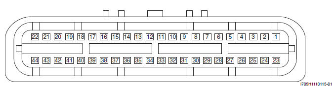
- Power source
- TO sensor signal (TOS)
- CKP sensor signal (CKP+)
- Sensor ground (E2)
- TP sensor signal (TP)
- IAP sensor signal (IAP)
- HO2 sensor signal (HO2)
- ECM ground (E1)
- CKP sensor signal (CKP-)
- -
- Power source for fuel injector (VM)
- STVA signal (STVA 1A)
- STVA signal (STVA 1B)
- Power source for sensors (Vcc)
- ISC valve motor signal (ISCA 2A)
- STVA signal (STVA 2B)
- STVA signal (STVA 2A)
- -
- Fuel pump relay (FP Relay)
- Fuel injector
- HO2 sensor heater
- Ignition coil
- Power source for back-up
- ECT sensor signal (ECT)
- IAT sensor signal (IAT)
- -
- -
- -
- STP sensor signal (STP)
- Starter relay
- SDS
- Mode select switch
- Speed sensor
- ISC valve motor signal (ISCA 1B)
- ISC valve motor signal (ISCA 1A)
- ISC valve motor signal (ISCA 2B)
- Meter communication
- -
- Immobilizer (For E-02, 19, 24, 54) communication
- Immobilizer (For E-02, 19, 24, 54) communication, Ignition signal
- -
- Tachometer
- ECM ground (E1)
- ECM ground (E3)
Component Location
FI System Parts Location
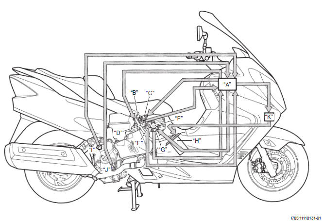
- ECM
- Fuel injector (FI)
- Idle speed control valve (ISC valve)
- Throttle position sensor (TPS)
- Secondary throttle position sensor (STPS)
- Secondary throttle valve actuator (STVA)
- Intake air temperature (IATS)
- Fuel pump (FP)
- Crankshaft position sensor (CKPS)
- Heated oxygen sensor (HO2S)
- Fuel pump relay (FP relay)
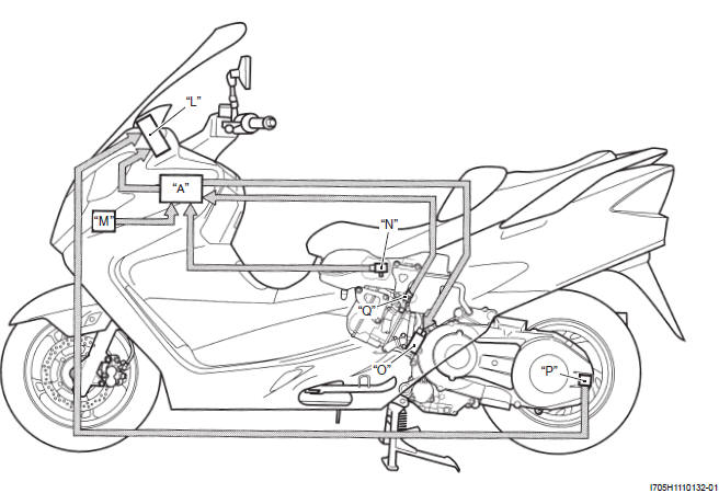
- Speedometer
- Tip-over sensor (TOS)
- Intake air pressure sensor (IAPS)
- Ignition coil (IG Coil)
- Speed sensor
- Engine coolant temperature sensor (ECTS)
See also:
 Suzuki Burgman 400 - Service manual > General Description
Injection Timing Description Injection Time (Injection Volume) The factors to determine the injection time include the basic fuel injection time which is calculated on the basis of the intake air pressure, engine speed and throttle opening angle, and various compensations. These compensations are determined according to the signals from various sensors that detect the engine and driving conditions.
Suzuki Burgman 400 - Service manual > Diagnostic Information and Procedures
Engine Symptom Diagnosis


