 Suzuki Burgman 400 - Service manual > General Description
Injection Timing Description
Injection Time (Injection Volume)
The factors to determine the injection time include the basic fuel injection time which is calculated on the basis of the intake air pressure, engine speed and throttle opening angle, and various compensations. These compensations are determined according to the signals from various sensors that detect the engine and driving conditions.
Compensation of Injection Time (Volume)
The following different signals are output from the respective sensors for compensation of the fuel injection time (volume).
Signal
ENGINE COOLANT TEMPERATURE SENSOR SIGNAL
- When engine coolant temperature is low, injection time (volume) is increased.
INTAKE AIR TEMPERATURE SENSOR SIGNAL
- When intake air temperature is low, injection time (volume) is increased.
HEATED OXYGEN SENSOR SIGNAL
- Air/fuel ratio is compensated to the theoretical ratio from density of oxygen in exhaust gasses. The compensation occurs in such a way that more fuel is supplied if detected air/fuel ratio is lean and less fuel is supplied if it is rich.
BATTERY VOLTAGE SIGNAL
- ECM operates on the battery voltage and at the same time, it monitors the voltage signal for compensation of the fuel injection time (volume). A longer injection time is needed to adjust injection volume in the case of low voltage.
ENGINE RPM SIGNAL
- At high speed, the injection time (volume) is increased.
STARTING SIGNAL
- When starting engine, additional fuel is injected during cranking engine.
ACCELERATION SIGNAL/ DECELERATION SIGNAL
- During acceleration, the fuel injection time (volume) is increased, in
accordance with the throttle opening speed and engine rpm.
During deceleration, the fuel injection time (volume) is decreased.
Injection Stop Control
TIP-OVER SENSOR SIGNAL (FUEL SHUT-OFF)
- When the motorcycle tips over, the tip-over sensor sends a signal to the ECM. Then, this signal cuts OFF current supplied to the fuel pump, fuel injectors and ignition coils.
OVER-REV. LIMITER SIGNAL
- The fuel injector stops operation when engine rpm reaches rev. limit rpm.
Self-Diagnosis Function
The self-diagnosis function is incorporated in the ECM. The function has two modes, "User mode" and "Dealer mode".
The user can only be notified by the LCD (DISPLAY) panel and LED (FI light). To check the function of the individual FI system devices, the dealer mode is provided. In this check, the special tool is necessary to read the code of the malfunction items.
User Mode
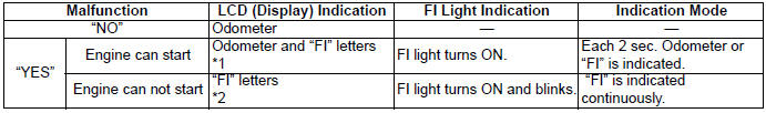
*1 When one of the signals is not received by ECM, the fail-safe circuit
works and injection is not stopped. In this case, "FI" and odometer are
indicated in the LCD panel and motorcycle can run.
*2 The injection signal is stopped, when the crankshaft position sensor signal,
tip-over sensor signal, ignition signal, injector signal, fuel pump relay signal
or ignition switch signal is not sent to ECM. In this case, "FI" is indicated in
the LCD panel. Motorcycle does not run.
"CHEC": The LCD panel indicates "CHEC" when no communication signal from the ECM is received for 5 seconds and more.
For Example: The ignition switch is turned ON, and the engine stop switch is turned OFF. In this case, the speedometer does not receive any signal from the ECM, and the panel indicates "CHEC".
If CHEC is indicated, the LCD does not indicate the trouble code. It is necessary to check the wiring harness between ECM and speedometer couplers.
The possible cause of this indication is as follows: Engine stop switch is in OFF position. Side-Stand/ignition inter-lock system is not working. Ignition fuse is burnt.
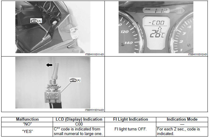
Dealer Mode
! CAUTION Before checking the malfunction code, do not disconnect the ECM coupler.
If the coupler from the ECM is disconnected, the malfunction code memory is erased and the malfunction code can not be checked.
The defective function is memorized in the computer. Use the special tool's coupler to connect to the dealer mode coupler (A). The memorized malfunction code is displayed on LCD (DISPLAY) panel. Malfunction means that the ECM does not receive signal from the devices. These affected devices are indicated in the code form.
Special tool (A): 09930-82720 (Mode select switch)
See also:
 Suzuki Burgman 400 - Service manual > Schematic and Routing Diagram
FI System Wiring Diagram Crankshaft position sensor (CKPS) Throttle position sensor (TPS) Intake air pressure sensor (IAPS) Secondary throttle position sensor (STPS) Engine coolant temperature sensor (ECTS) Intake air temperature sensor (IATS) Tip-over sensor (TOS) HO2 sensor Fuel injector Fuel pump (FP) Fuel pump relay (FP relay) Ignition coil Speed sensor Idle speed control valve (ISC valve) Secondary throttle valve actuator (STVA) Engine stop switch Side-stand relay Ignition switch Starter button Brake light switch Brake relay Side-stand switch Starter relay Starter motor Battery SDS


