 Suzuki Burgman 400 - Service manual > ECT Sensor Removal and Installation
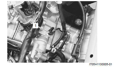
Removal
1) Remove the air cleaner box. Refer to "Air Cleaner Box Removal and Installation".
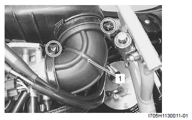
2) Disconnect the coupler and remove the ECT sensor (1).
Installation
Install the ECT sensor in the reverse order of removal.
Pay attention to the following point:
- Tighten the ECT sensor to the specified torque.
Tightening torque
ECT sensor: 12 N*m (1.2 kgf-m, 8.5 lb-ft)
Speed Sensor Inspection
Inspect the speed sensor. Refer to "DTC "C16" (P0500): Speed Sensor".
Speed Sensor Removal and Installation
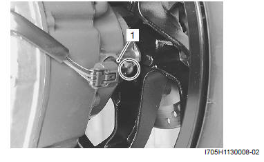
Removal
1) Remove the outer clutch cover. Refer to "V-belt Type Continuously Variable Automatic Transmission Removal and Installation".
2) Disconnect the coupler and remove the speed sensor (1).
Installation
Install the speed sensor in the reverse order of removal.
IAT Sensor Inspection
Inspect the IAT sensor in the following procedures:
1) Remove the IAT sensor. Refer to "IAT Sensor Removal and Installation".
2) Inspect the IAT sensor resistance. If the value dose not change in the proportion indicated, replace the IAT sensor with a new one.
NOTE IAT sensor resistance measurement method is the same way as that of ECT sensor. Refer to "ECT Sensor Inspection".
3) Install the IAT sensor. Refer to "IAT Sensor Removal and Installation".
IAT Sensor Removal and Installation
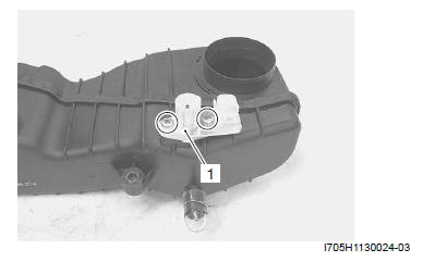
Removal
1) Remove the air cleaner box. Refer to "Air Cleaner Box Removal and Installation".
2) Remove the IAT sensor (1).
Installation
Install the IAT sensor in the reverse order of removal.
Pay attention to the following point:
- Tighten the IAT sensor mounting screw to the specified torque.
Tightening torque
IAT sensor mounting screw: 3.5 N*m (0.35 kgf-m, 2.5 lb-ft)
TO Sensor Inspection
Inspect the TO sensor. Refer to "DTC "C23" (P1651-H/ L): TO Sensor Circuit Malfunction".
TO Sensor Removal and Installation
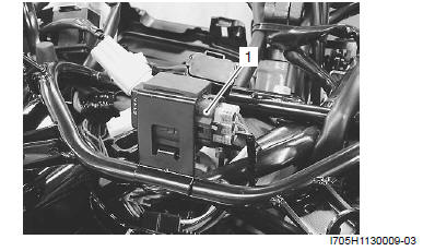
Removal
1) Remove the meter panel. Refer to "Meter Panel Removal and Installation".
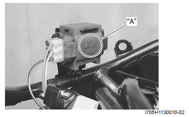
2) Disconnect the coupler and remove the TO sensor (1).
Installation
Install the TO sensor in the reverse order of removal.
Pay attention to the following point:
- When installing the TO sensor, bring the "UPPER" letters and arrow mark "A" upward.
STP Sensor Inspection
Inspect the STP sensor. Refer to "DTC "C29" (P1654-H/ L): Secondary Throttle Position Sensor (STPS)".
STP Sensor Adjustment
Adjust the STP sensor in the following procedures:
1) Remove the helmet box front cover. Refer to "Helmet Box Front Cover Removal and Installation".
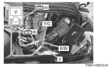
2) Remove the air cleaner box outlet tube (1).
3) Disconnect the STVA lead wire coupler (2).
4) Turn the ignition switch ON.
5) Insert the needle pointed probes to the STP sensor coupler.
STP sensor output voltage
ST valve is fully closed: 0.5 V
ST valve is fully open: 3.9 V
(Positive terminal: Y/G - Negative terminal: B/Br)
Special tool
(A): 09900-25008 (Multi-circuit tester set)
(B): 09900-25009 (Needle pointed probe set)
Tester knob indication
Voltage ( )
)
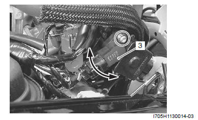
6) Close the STV by finger, and measure the STP sensor output voltage. If the output voltage is out of the value, loosen the STP sensor mounting screw.
7) Adjust the STP sensor (3) until the output voltage comes within the specified value and tighten the STP sensor mounting screw.
Special tool : 09930-11950 (Torx wrench)
8) Install the removed parts.
See also:
 Suzuki Burgman 400 - Service manual > CKP Sensor Removal and Installation
Removal 1) Drain engine oil. Refer to "Engine Oil and Filter Change". 2) Remove the muffler. Refer to "Exhaust Pipe / Muffler Removal and Installation".
Suzuki Burgman 400 - Service manual > STP Sensor Removal and Installation
Removal 1) Remove the helmet box front cover. Refer to "Helmet Box Front Cover Removal and Installation". 2) Disconnect the coupler and remove the STP sensor (1).


