 Suzuki Burgman 400 - Service manual > STP Sensor Removal and Installation
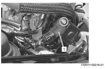
Removal
1) Remove the helmet box front cover. Refer to "Helmet Box Front Cover Removal and Installation".
2) Disconnect the coupler and remove the STP sensor (1).
Installation
Install the STP sensor in the reverse order of removal.
Pay attention to the following point:
- Adjust the position of STP sensor. Refer to "STP Sensor Adjustment".
ISC Valve Inspection
Inspect the ISC valve. Refer to "DTC "C40" (P0505, P0506 or P0507): ISC Valve Circuit Malfunction".
ISC Valve Removal and Installation
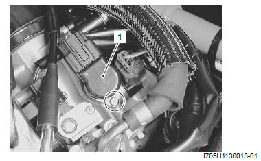
Removal
1) Remove the helmet box front cover. Refer to "Helmet Box Front Cover Removal and Installation".
2) Disconnect the coupler and screw.
3) Remove the ISC valve (1).
Installation
Install the ISC valve in the reverse order of removal.
ISC valve pre-set
When removing or replacing the ISC valve, set the ISC valve to the following procedures:
Procedure
1) Turn the ignition switch to OFF position.
2) Remove the upper meter panel. Refer to "Upper Meter Panel Removal and Installation".
3) Connect the special tool to the dealer mode coupler and turn its switch to ON position. Refer to "Self- Diagnostic Procedures".
Special tool : 09930-82720 (Mode select switch)
4) Open the throttle valve fully and turn the ignition switch to ON position.
5) Then, wait more than 10 seconds while holding the 4) condition.
6) Close the throttle valve and turn the ignition switch to OFF position.
NOTE The ISC valve is automatically set at PRESET position.
7) Turn the special tool to OFF position and remove it from the dealer mode coupler.
8) Install the upper meter panel. Refer to "Upper Meter Panel Removal and Installation ".
HO2 Sensor Inspection
Inspect the HO2 sensor. Refer to "DTC "C44" (P0130, P0135): HO2 Sensor (HO2S) Circuit Malfunction".
HO2 Sensor Removal and Installation
Refer to "Heated Oxygen Sensor (HO2S) Removal and Installation".
Specifications
Service Data
FI Sensors

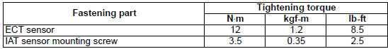
Tightening Torque Specifications
Reference: For the tightening torque of fastener not specified in this section, refer to "Tightening Torque Specifications ".
Special Tools and Equipment
Special Tool
 09900-25008
Multi-circuit tester set
09900-25008
Multi-circuit tester set
 09900-25009
Needle pointed probe set
09900-25009
Needle pointed probe set
 09930-11950
Torx wrench
09930-11950
Torx wrench
 09930-82720
Mode select switch
09930-82720
Mode select switch
See also:
 Suzuki Burgman 400 - Service manual > ECT Sensor Removal and Installation
Removal 1) Remove the air cleaner box. Refer to "Air Cleaner Box Removal and Installation". 2) Disconnect the coupler and remove the ECT sensor (1).


