 PIAGGIO Beverly 300ie - Service manual > Electrical system installation
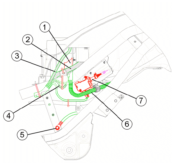
Front side
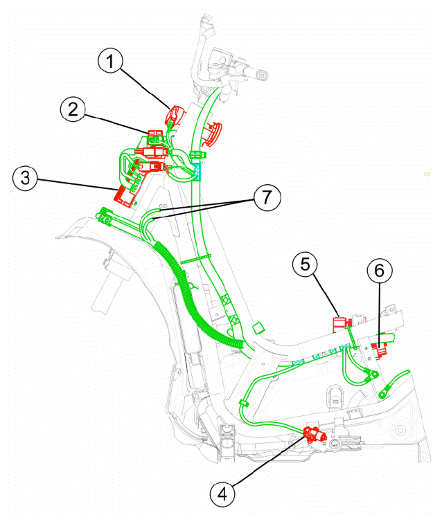
- Ignition switch hood
- Turn indicator control device
- Voltage regulator
- Side stand switch
- Overturn sensor
- HV coil
- Front L turn indicator and daylight running lights
- Electric fan connection
- Side stand connection
- Overturn sensor
- HV coil
- Stator connection
- Immobilizer aerial
- Low voltage power socket accessories in the front top box
- To the front right turn indicator and daylight running lights
- External air temperature sensor
- Boost cable connection (only in version 125)
- Flywheel - regulator connection
- To instrument panel
- To headlight
- To the left stop button
- to the right stop button
- Horn
- Fuel pump connection
- Voltage regulator
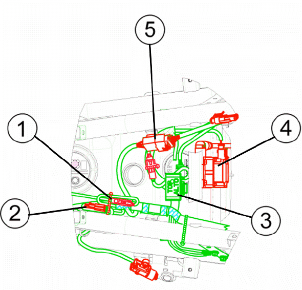
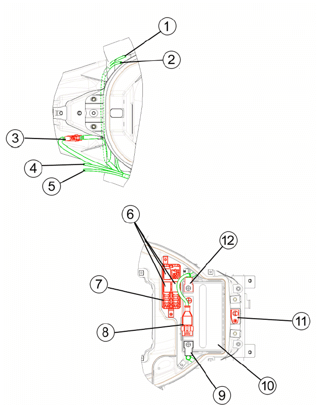
Back side
- License plate light connection
- To the right headlamp
- To the right turn indicator
- Helmet compartment lighting to the light unit
- Pick-up connection
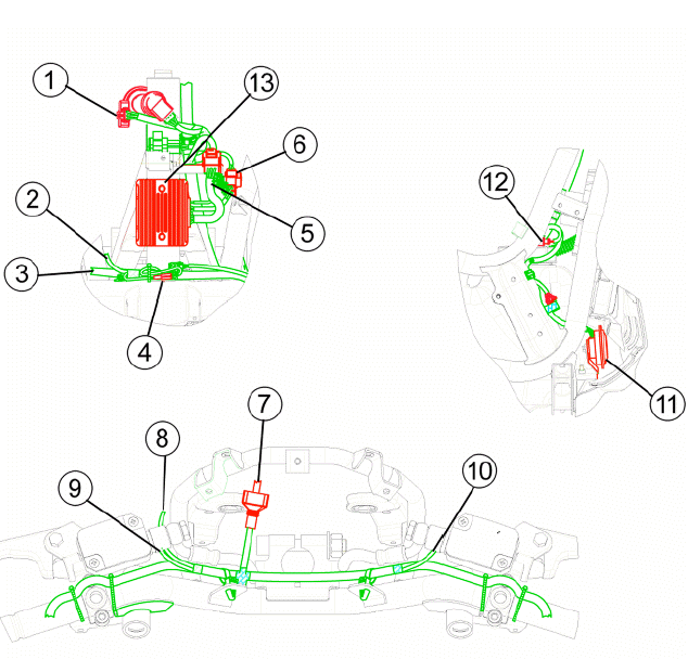
- Flywheel cables
- Cables to the motor
- To the license plate lightening
- Starter relay
- To the fuse holder terminal block
- To battery positive
- To the starter relay
- Ground point
- Starter motor positive cable
- Saddle opening actuator
- To the left turn indicator
- To the left headlamp
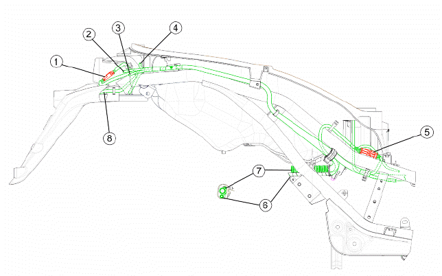
- License plate light connection
- To the right turn indicator
- To the right headlamp
- Micro-relay
- Rear fuse-box
- Diagnostics socket
- Negative battery pole
- Battery 12V 10Ah
- Helmet compartment light switch
- Positive battery pole
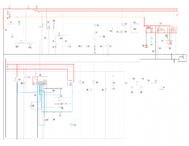
Conceptual diagrams
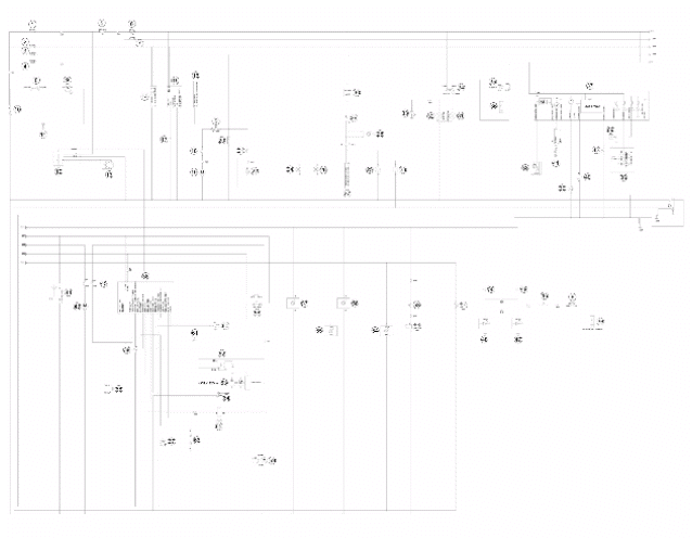
BASIC CIRCUIT DIAGRAM LEGEND:
- F01-30A
- F02-15A
- F03-10A
- F04-15A
- Starter switch
- F05-10A
- F06-5A
- Starter solenoid
- Starter motor
- 12V - 10Ah Battery
- Chassis ground
- Regulator
- Flywheel
- Antitheft
- Provision for actuator control receiver
- Antitheft
- Reset receiver radio
- Saddle button
- Actuator
- LV socket
- Helmet compartment light button
- Light unit
- Rear right turn indicator
- Rear left turn indicator
- Front right hand turn indicator
- Front left hand turn indicator
- Antitheft
- Turn indicator warning light
- Turn indicator switch
- turn indicator control
- Low beam light bulb
- High beam light bulb
- High beam indicator light
- Light switch
- Headlight solenoid
- Electronic control unit
- Instrument panel
- Fuel gauge
- Engine temperature
- Ambient temperature sensor
- Speed sensor
- Mode button
- Electric fan
- Immobilizer aerial
- Electric fan solenoid
- Starter button
- Right hand stop light bulb
- Left hand stop light bulb
- Stop button
- Stop button
- License plate lighting bulb
- Horn
- Horn button
- Rear right hand turn indicator bulb
- Rear left hand turn indicator bulb
- Front right hand turn indicator bulb
- Front left hand turn indicator bulb
- Injection load solenoid
- Fuel pump
- Engine stop switch
- Stand button (raised position)
- HV coil
- Water pump (125ie version only)
- Diagnostics socket
- Fuel injector
- Overturn sensor
- Lambda probe
- Pickup
- Oil pressure sensor
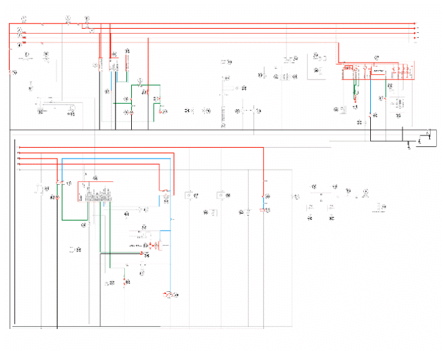
Ignition

BASIC CIRCUIT DIAGRAM LEGEND:
1.F01-30A
3.F03-10A
4.F04-15A
5.Starter switch
6.F05-10A
7.F06-5A
10.12V - 10Ah Battery
11.Chassis ground
36.Electronic control unit
37.Instrument panel
43.Electric fan
58.Injection load solenoid
60.Engine stop switch
61.Stand button (raised position)
62.HV coil
Battery recharge and starting
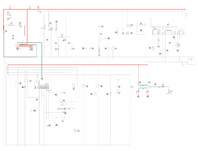
BASIC CIRCUIT DIAGRAM LEGEND:
1.F01-30A
5.Starter switch
6.F05-10A
8.Starter relay
9.Starter motor
10.12V - 10 Ah Battery
11.Chassis ground
12.Regulator
13.Flywheel
36.Electronic control unit
46.Starter button
47.Right stop light bulb
48.Left stop light bulb
49.Stop button
50.Stop button
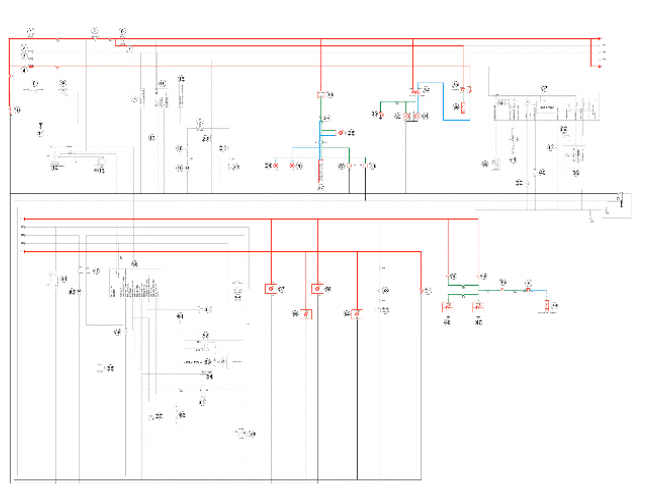
Level indicators and enable signals section
BASIC CIRCUIT DIAGRAM LEGEND:
1.F01-30A
2.F02-15A
3.F03-10A
4.F04-15A
5.Starter switch
6.F05-10A
7.F06-5A
10.12V - 10Ah Battery
36.Electronic control unit
37.Instrument panel
38.Fuel gauge
39.Engine temperature sensor
44.Immobilizer aerial
58.Injection load solenoid
60.Engine stop switch
61.Stand button (raised position)
65.Fuel injector
67.Lambda probe
68.Pickup
69.Oil pressure sensor
Devices and accessories
BASIC CIRCUIT DIAGRAM LEGEND:
1.F01-30A
2.F02-15A
3. F03-10A
4.F04-15A
5.Starter switch
6.F05-10A
7.F06-5A
10.12V - 10Ah Battery
14.Antitheft
15.Provision for actuator control receiver
16.Antitheft
17.Reset receiver radio
18.Saddle button
19.Actuator
20.LV socket
21.Helmet compartment light button
22.Light unit
37.Instrument panel
40.Ambient temperature sensor
41.Speed sensor
42.Mode button
43.Electric fan
45.Electric fan solenoid
52.Horn
53.Horn button
58.Injection load solenoid
59.Fuel pump
63.Water pump (125ie version only)
64.Diagnostics socket
66.Overturn sensor
Lights and turn indicators
BASIC CIRCUIT DIAGRAM LEGEND:
1.F01-30A
4.F04-15A
5.Starter switch
6.F05-10A
7.F06-5A
10.12V - 10Ah Battery
11.Chassis ground
23.Rear right turn indicator
24.Rear left turn indicator
25.Front right turn indicator
26.Front left turn indicator
27.Antitheft
28.Turn indicator warning light
29.Turn indicator switch
30.turn indicator control
31.Low beam light bulb
32.High beam light bulb
33.High beam warning light
34.Light switch
35.Headlight solenoid
36.Electronic control unit
46.Starter button
47.Right stop light bulb
48.Left stop light bulb
49.Stop button
50.Stop button
51.License plate lighting bulb
54.Rear right turn indicator bulb
55.Rear left turn indicator bulb
56.Front right turn indicator bulb
57.Front left turn indicator bulb
See also:
 PIAGGIO Beverly 300ie - Service manual > Components arrangement
Starter switch: remove the legshield to reach them. Immobilizer antenna: remove the legshield to reach them. Regulator connector: remove the legshield to reach them. Spark plug: remove the spark plug inspection cover to access the spark plug. Battery: lift the saddle and remove the battery cover to access the battery. Fuses: lift the saddle and remove the battery cover to access the battery. relays: lift the saddle and remove the battery cover to access the battery. Diagnostic socket: lift the saddle and remove the battery cover to access the battery. Control unit: lift the saddle and remove the engine inspection cover to access the ECU. Saddle actuator: to reach it, remove the left fairing. H.V. coil: remove the helmet compartment to reach it. Starter relay: to reach it, remove the left fairing. Stand button: remove the left footrest to reach it. Stator connector: remove the central chassis cover to reach them. Roll-over sensor: remove the central chassis cover to reach them. Fuel pump: remove the central chassis cover to reach them. Fuel level transmitter: remove the central chassis cover to reach them. Horn: remove the front wheel housing to reach it. Temperature sensor: remove the legshield to reach them. LV socket: remove the legshield to reach them. Regulator: remove the legshield to reach them. Turn indicator device: remove the legshield to reach them.
PIAGGIO Beverly 300ie - Service manual > Checks and inspections
This section is dedicated to the checks on the electrical system components. Immobiliser The electronic ignition system is controlled by the control unit with the integrated Immobilizer system.


