 PIAGGIO Beverly 300ie - Service manual > Checks and inspections
This section is dedicated to the checks on the electrical system components.
Immobiliser
The electronic ignition system is controlled by the control unit with the integrated Immobilizer system.
The immobilizer is an anti-theft system that allows the vehicle to be operated only when it is started with coded keys recognised by the control unit. The code is integrated in a transponder in the key block.
This allows the driver clear operation without having to do anything other than just turning the key. The Immobilizer system consists of the following components:
- an electronic control unit
- immobilizer aerial
- master key with built-in transponder
- service key with built-in transponder
- diagnosis LED
The diagnosis LED also works as a theft-deterrent blinker. This function is activated every time the key switch is set to "OFF" or the engine emergency cut-off switch is set to "OFF". It remains activated for 48 hours in order not to affect the battery charge. When the ignition switch is turned to "ON", the deterring blinker function is deactivated. Subsequently, a flash confirms the switching to " ON". The duration of the flash depends on the programming of the electronic control unit If the LED is off regardless of the position of the ignition-key switch and/or the instrument panel is not initiated, check if:
- there is battery voltage
- fuses No. 1; 2; 6 and 9 are in working order
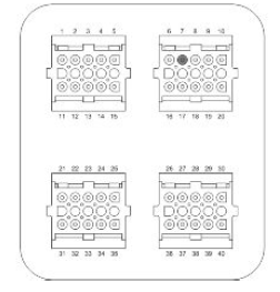
- there is power to the control unit as specified below:
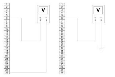
2 With the key switch set to OFF:
- if there is battery voltage between terminals 6-26 and terminal
6-chassis ground (fixed power supply).
If there is no voltage, check that fuse 6 and its cable harness are in working order.
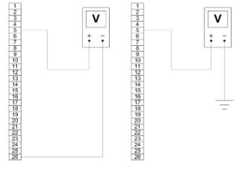
With the key switch in the OFF position:
- if there is battery voltage between terminals 5-26 and terminals
5-chassis ground (fixed power supply).
If there is no voltage, check the key switch contacts, and that fuses No. 1 and 9 and their cable harnesses are in working order.
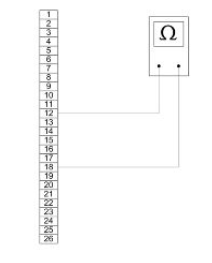
- There is continuity between terminals 12-18 and the emergency cut-off switch is set to "RUN" and the side stand is folded up. If there is no continuity, check the contacts of the latter.
After removing the leg shield back plate, remove the electrical connection from the aerial as shown in the picture.
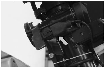
Remove the protective base from the connector.
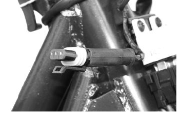
With the ignition key switch at "ON" check if there is battery voltage between the Red-White and Black cables
With MIU connector disconnected, check the continuity between the Orange-White cable and pin 7 of the interface wiring.
Specific tooling
020481Y Control unit interface wiring
020331Y Digital multimeter
Virgin circuit
When the ignition system is not encrypted, any key will start the engine but limited to 2000 rpm. The keys can only be recognised if the control unit has been programmed properly. The data storage procedure for a previously not programmed control unit provides for the recognition of the Master as the first key to be stored to memory: this becomes particularly important because it is the only key that enables the control unit to be wiped clean and reprogrammed for the memorisation of the service keys.
The Master and service keys must be used to code the system as follows:
- Insert the Master key, turn it to "ON" and keep this position for two seconds (lower and upper limits 1 to 3 seconds).
- Insert the service key and turn it to "ON" for 2 seconds.
- If you have copies of the key, repeat the operation with each key.
- Insert the MASTER key again and turn it to "ON" for 2 seconds.
The maximum time to change keys is 10 seconds.
A maximum of 7 service keys can be programmed at one time.
It is essential to adhere to the times and the procedure. If you do not, start again from the beginning.
Once the system has been programmed, the Master key transponder is strictly matched with the control unit. With this link established, it is now possible to encode new service keys, in the event of losses, replacements, etc. Each new programming deletes the previous one; to add or delete a key it is therefore necessary to repeat the procedure using all the keys that you intend to keep in use. If a service key becomes uncoded, the efficiency of the high voltage circuit shielding must be thoroughly inspected: In any case it is advisable to use resistor spark plugs.
Diagnostic codes
The Immobilizer system is tested each time the key switch is turned from "OFF" to "ON". During this diagnosis phase a number of control unit statuses can be identified and various light codes displayed. Regardless of the code transmitted, if at the end of the diagnosis the LED remains off permanently, the ignition is enabled. If, however, the LED remains on permanently, it means the ignition is inhibited:
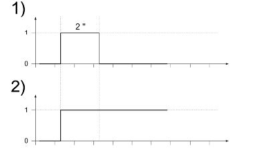
1. Previously unused control unit - key inserted: a single 2 second flash is displayed, after which the LED remains off permanently. The keys can be stored to memory, the vehicle can be started but with a limitation imposed on the number of revs.
2. Previously unused control unit - transponder absent or cannot be used: The LED is permanently ON; in this condition, no operations are possible, not even starting the vehicle.
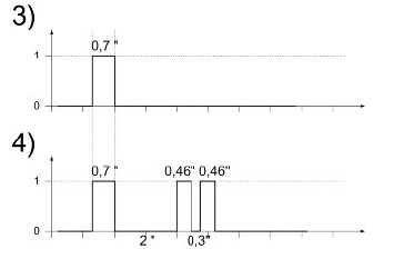
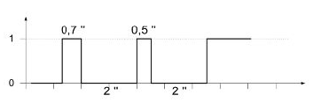
3. Programmed control unit - service key inserted (normal conditions of use): a single 0.7 second flash is displayed, after which the LED remains off permanently. The engine can be started.
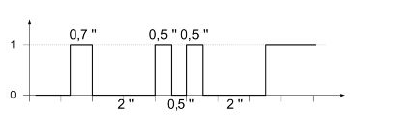
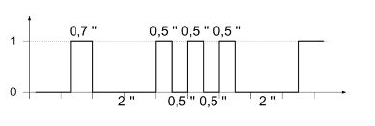
4. Programmed control unit - Master key inserted: a 0.7-sec flash is displayed followed by the LED remaining off for 2 sec and then by short 0.46- sec flashes, the same number of times as there are keys stored in the memory including the Master key. When the diagnosis has been completed, the LED remains permanently OFF. The engine can be started.
5. Programmed control unit - fault detected: a light code is displayed according to the fault detected, after which the LED remains on permanently. The engine cannot be started. The codes that can be transmitted are:
- 1-flash code
- 2-flash code
- 3-flash code
Diagnostic code - 1 flash
A one-flash code indicates a system where the serial line is not present or is not detected. Check the Immobilizer aerial wiring and change it if necessary.
Diagnostic code - 2 flashes
A two-flash code shows a system where the control unit does not show the transponder signal. This might depend on the inefficiency of the immobiliser aerial or the transponder.
Turn the switch to "ON" using several keys: if the code is repeated even with the Master key, check the aerial wiring and change it if necessary. If this is not the case, replace the defective key and/or reprogram the control unit.
Diagnostic code - 3 flashes
A three-flash code indicates a system where the control unit does not recognise the key. Turn the switch to "ON" using several keys: if the error code is repeated even with the Master key, replace the control unit. If this is not the case, reprogram the decoder.
See also:
 PIAGGIO Beverly 300ie - Service manual > Electrical system installation
Front side Ignition switch hood Turn indicator control device Voltage regulator Side stand switch Overturn sensor HV coil Front L turn indicator and daylight running lights Electric fan connection Side stand connection Overturn sensor HV coil Stator connection Immobilizer aerial Low voltage power socket accessories in the front top box To the front right turn indicator and daylight running lights External air temperature sensor Boost cable connection (only in version 125) Flywheel - regulator connection To instrument panel To headlight To the left stop button to the right stop button Horn Fuel pump connection Voltage regulator
PIAGGIO Beverly 300ie - Service manual > Ignition circuit
No spark plug WARNING ALL CONTINUITY TESTS MUST BE CARRIED OUT WITH THE CORRESPONDING CONNECTORS DISCONNECTED. HV coil primary resistance value:


