 PIAGGIO Beverly 300ie - Service manual > Ignition circuit
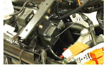
No spark plug
WARNING
ALL CONTINUITY TESTS MUST BE CARRIED OUT WITH THE CORRESPONDING CONNECTORS DISCONNECTED.
HV coil primary resistance value:
Disconnect the connector of the HV coil and measure the resistance between the two terminals.
Characteristic
HV coil resistance primary value:
- 0.9 Ω
HV coil secondary resistance value:
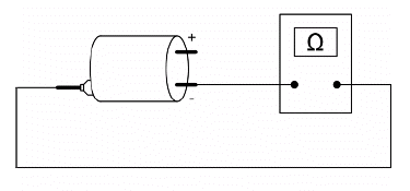
1) Disconnect the HV cable from the spark plug and measure the resistance between the spark plug cap and the HV coil negative terminal.
2) Disconnect the spark plug cap from the HV cable and measure the resistance between the HV cable end and the HV coil negative terminal (see figure).
3) Measure the resistance between the 2 ends of the spark plug cap.
Characteristic
HV coil secondary resistance value with spark plug cap
- 8.4 kΩ
HV coil secondary resistance value:
- 3.4 kΩ
Spark plug cap resistance value
- 5 kΩ
Battery recharge circuit
The charging circuit consists of three-phase alternator and a permanent magneto flywheel.
The generator is directly connected to the voltage regulator.
This, in its turn, is connected directly to the ground and the battery positive terminal passing through the 30A protective fuse.
The three-phase alternator provides good recharge power and at low revs a good compromise is achieved between generated power and idle stability.
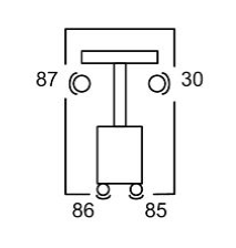
Remote controls check
To check the operation of a solenoid:
1) Check that, given regular conditions, there is no continuity between terminals 87 and 30.
2) Apply a 12V voltage to power terminals 86 and 85 of the solenoid.
3) With the solenoid fed, check that there is continuity between terminals 87 and 30.
4) If these conditions are not met, the solenoid is surely damaged and, therefore, it should be replaced.
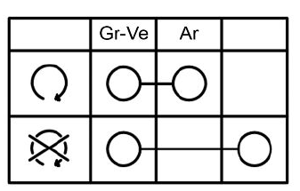
Switches check
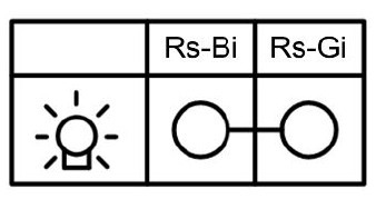
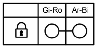
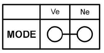
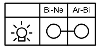
To check buttons and switches, check that, according to their position, the continuity of contacts is correct as indicated in the following charts.
KEY
Ar: Orange Az: Sky Blue Bi: White Bl: Blue Gi: Yellow Gr: Grey Ma: Brown Ne: Black Ro: Pink Rs: Red Ve: Green Vi: Purple
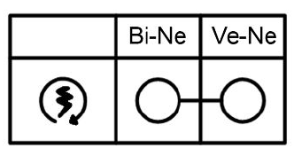
ENGINE STOP SWITCH
STARTER BUTTON
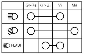
LIGHT SWITCH
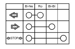
TURN INDICATOR SWITCH
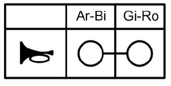
HORN BUTTON
HELMET COMPARTMENT LIGHT SWITCH
SADDLE OPENING SWITCH
MODE BUTTON
STAND BUTTON

STOP BUTTONS
Stator check
Checking the stator windings
WARNING
THIS CHECK-UP CAN BE MADE WITH THE STATOR PROPERLY INSTALLED.
1) Remove the right side panel.
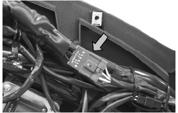
2) Disconnect the connector between stator and regulator with the three yellow cables as shown in the picture.
3) Measure the resistance between each of the yellow terminals and the other two.
4) Check that there is insulation between the each yellow cable and the ground.
Electric characteristic
Resistance:
0.2 - 1 Ω
Voltage regulator check
With a perfectly charged battery and lights off, measure voltage at the battery poles with a high running engine.
Voltage should not exceed 15 Volt.
In case higher voltages are detected, replace the regulator.
In case of voltage values lower than 14 Volt, check the stator and the corresponding cable harness.
Electric characteristic
Control voltage
14÷15 V to 1500÷12000 rpm
Recharge system voltage check
Look for any leakage
1) Access the battery by removing its cover under the saddle.
2) Check that the battery does not show signs of losing fluid before checking the output voltage.
3) Turn the ignition key to "OFF", connect the multimeter leads between the battery negative pole (-) and the Black cable. Only then disconnect the Black cable from the battery negative pole (-).
4) With the ignition key always "OFF", the reading indicated by the ammeter must be must be ≤ 0.5 mA.
Charging current check
WARNING
BEFORE CARRYING OUT THE CHECK, MAKE SURE THAT THE BATTERY IS IN GOOD WORKING ORDER.
1) Place the vehicle on its centre stand.
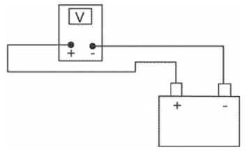
2) With the battery correctly connected to the circuit, place the multimeter leads between the battery terminals.
3) Turn on the engine, increase the engine rpm and, at the same time, measure the voltage.
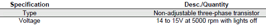
Electric characteristic
Voltage ranging between 14.0 and 15.0V at 5000 rpm.
Maximum current output check.
- With the engine off and the panel at "ON" with the lights on, allow the battery voltage to stop at 12V.
- Connect ammeter pliers to the 2 recharge positive poles in output from the regulator.
- Start the engine and rev it up to a high engine speed while reading the value on the pincer.
With an efficient battery a value must be detected: > 20A
VOLTAGE REGULATOR/RECTIFIER
See also:
 PIAGGIO Beverly 300ie - Service manual > Checks and inspections
This section is dedicated to the checks on the electrical system components. Immobiliser The electronic ignition system is controlled by the control unit with the integrated Immobilizer system.
PIAGGIO Beverly 300ie - Service manual > Starter motor
KEY Starter motor Starter relay Battery Fuse No. 1 Ignition switch contacts Fuse No. 5 Stop buttons Starter button Injection ECU


