 PIAGGIO Beverly 300ie - Service manual > Starter motor
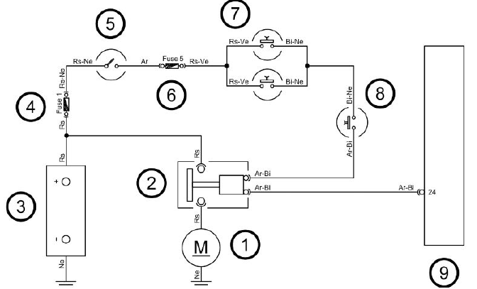
KEY
- Starter motor
- Starter relay
- Battery
- Fuse No. 1
- Ignition switch contacts
- Fuse No. 5
- Stop buttons
- Starter button
- Injection ECU
WARNING
ALL CONTINUITY TESTS MUST BE CARRIED OUT WITH THE CORRESPONDING CONNECTORS DISCONNECTED.
1) Check if there is continuity of the Red cable connecting the battery, the start-up solenoid and the starter motor.
2) Check fuses No. 1 and 5, the ignition key contacts, the stop light buttons and the starter button.
3) Check the start-up solenoid.
4) If components are in good condition, check that the cable harness connecting them is not interrupted.
5) Check if there is continuity of the Orange-Blue cable between the start-up solenoid and the control unit connector.
Horn control
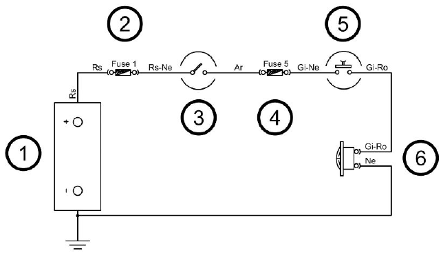
KEY
- Battery
- Fuse No. 1
- Ignition switch contacts
- Fuse No. 5
- Horn button
- Horn
WARNING
ALL CONTINUITY TESTS MUST BE CARRIED OUT WITH THE CORRESPONDING CONNECTORS DISCONNECTED.
1) Check fuses No. 1 and 5, the ignition key contacts and the horn button.
2) If the components are not damaged, check wiring for continuity.
3) Check that the Yellow-Pink cable between the horn and horn button is not interrupted.
4) Check that the Black cable of the horn is grounded.
Turn signals system check
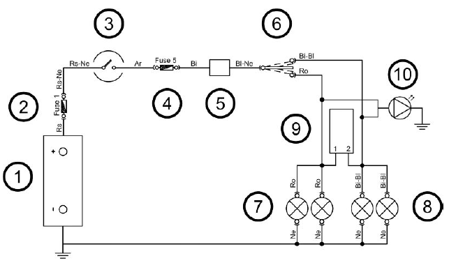
KEY
- Battery
- Fuse No. 1
- Ignition switch contacts
- Fuse No. 5
- Turn indicator control device
- Turn indicator switch
- Left turn indicators
- Right turn indicators
- Antitheft
- Warning light bulb
WARNING
ALL CONTINUITY TESTS MUST BE CARRIED OUT WITH THE CORRESPONDING CONNECTORS DISCONNECTED.
1) Check the working order of bulbs.
2) Check fuses No. 1 and 5 and the ignition key contacts.
3) Check if there is intermittent voltage between the Blue-Black cable of the turn indicator control device and the ground connection.
4) If there is no voltage, check that the cable harness is not interrupted.
5) Check the turn indicator switch.
6) Check that the Blue-Black cable between the turn indicator control device and the turn indicator switch is not interrupted.
7) Check that the Pink and White-Blue cables connecting the bulbs and the turn indicator switches are not interrupted.
8) Check the bulbs ground connection.
level indicators
WARNING
ALL CONTINUITY TESTS MUST BE CARRIED OUT WITH THE CORRESPONDING CONNECTORS DISCONNECTED.
If faults are detected:
1) With a multimeter, check resistance values between the White-Green cable and the Black cable of the fuel level transmitter by moving the arm with the float.
2) If the transmitter operates correctly but the indication on the instrument panel is not exact, check that the cable harnesses between them are not interrupted.
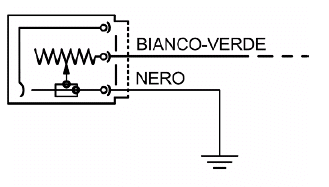
Electric characteristic
Resistance value when the tank is full
<= 7 Ω
Resistance value when the tank is empty
90 +13/-3 Ω
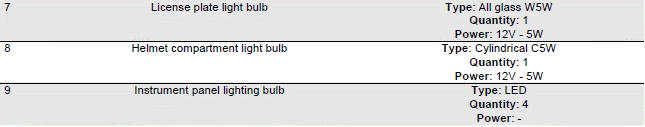
Lights list
BULBS
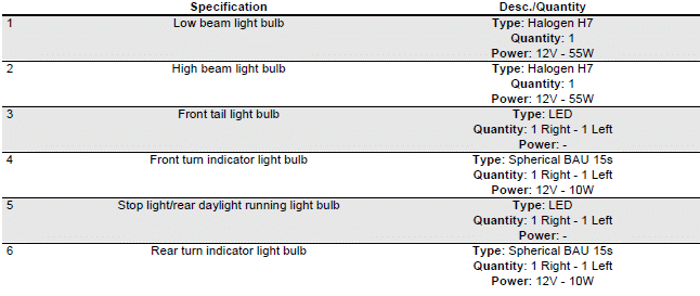
Line for daylight running lights and instrument panel lighting line
In the event of a malfunction, check:
- Efficiency of the bulbs
- Fuses No. 1 and 5
- Ignition key contacts
- Cable harness continuity
High beam/low beam light line
In the event of a malfunction, check:
- Efficiency of the bulbs
- Light switch
- Headlight from solenoid
- Fuses No. 1, 4, 5 and 6
- Ignition key contacts
- Cable harness continuity
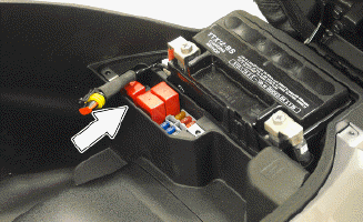
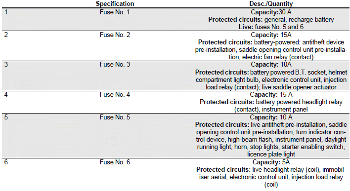
Fuses
The electrical system is equipped with 6 protection fuses located below the saddle. Open the saddle as described above.
Unscrew the three screws "A" and remove the cover "B".
The chart shows the position and specifications of the fuses in the vehicle.
CAUTION
BEFORE REPLACING A BLOWN FUSE, FIND AND SOLVE THE FAILURE THAT CAUSED IT TO BLOW. NEVER TRY TO REPLACE THE FUSE WITH ANY OTHER MATERIAL (E.G., A PIECE OF ELECTRIC WIRE).
CAUTION
MODIFICATIONS OR REPAIRS TO THE ELECTRICAL SYSTEM, PERFORMED INCORRECTLY OR WITHOUT STRICT ATTENTION TO THE TECHNICAL SPECIFICATIONS OF THE SYSTEM CAN CAUSE MALFUNCTIONING AND RISK OF FIRE.
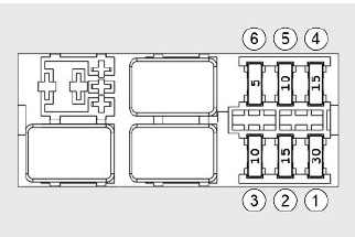
FUSES
Dashboard
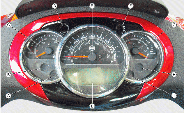
A= High beam warning light
B = Turn indicator warning lights
C = Fuel gauge
D = Low fuel warning light
E = Speedometer
F = Immobiliser LED
G = Coolant temperature gauge
H = Engine control telltale light
I = Engine oil pressure warning light
L = Digital display
Sealed battery
If the vehicle is provided with a sealed battery, the only maintenance required is the check of its charge and recharging, if necessary.
These operations should be carried out before delivering the vehicle, and on a six-month basis while the vehicle is stored in open circuit.
Besides upon pre-delivery it is therefore necessary to check the battery charge and recharge it, if required, before storing the vehicle and afterwards every six months.
INSTRUCTIONS FOR THE BATTERY REFRESH AFTER OPEN-CIRCUIT STORAGE
1) Voltage check
Before installing the battery on the vehicle, check the open circuit voltage with a standard tester.
- If voltage exceeds 12.60 V, the battery can be installed without any renewal recharge.
- If voltage is below 12.60 V, a renewal recharge is required as explained in 2).
2) Constant voltage battery charge mode
- Constant voltage charge equal to 14.40 to 14.70V
- Initial charge voltage equal to 0.3 to 0.5 for Nominal capacity
- Charge time:
10 to 12 h recommended
Minimum 6 h
Maximum 24 h
3) Constant current battery charge mode
- Charge current equal to 1/10 of the battery rated capacity
- Charge time: Maximum 5 h
See also:
 PIAGGIO Beverly 300ie - Service manual > Ignition circuit
No spark plug WARNING ALL CONTINUITY TESTS MUST BE CARRIED OUT WITH THE CORRESPONDING CONNECTORS DISCONNECTED. HV coil primary resistance value:
PIAGGIO Beverly 300ie - Service manual > Battery installation
VRLA battery (valve-regulated lead-acid battery) Maintenance Free (MF) WARNING BATTERY ELECTROLYTE IS TOXIC AND IT MAY CAUSE SERIOUS BURNS. IT CONTAINS SULPHURIC ACID. AVOID CONTACT WITH YOUR EYES, SKIN AND CLOTHING. IN CASE OF CONTACT WITH YOUR EYES OR SKIN, RINSE WITH ABUNDANT WATER FOR ABOUT 15 MINUTES AND SEEK IMMEDIATE MEDICAL ATTENTION.


