 Yamaha XMAX YP125R - Service manual > Engine (left side view)
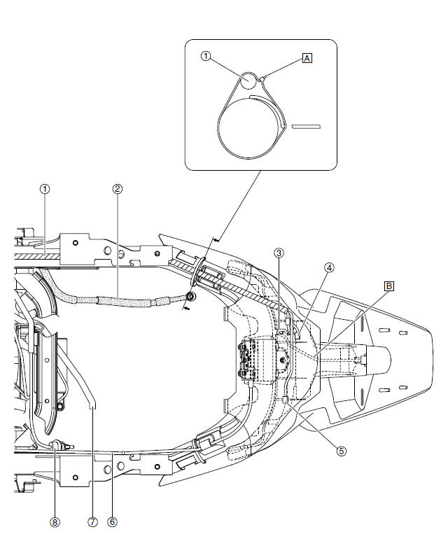
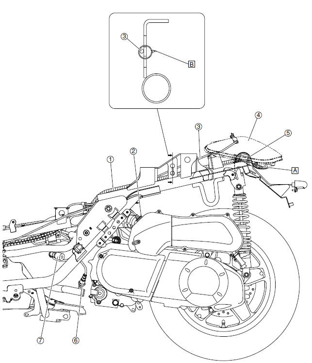
- Wire harness
- Intake air temperature sensor
- Seat lock cable
- Left tail/brake light assembly
- Safety protector
- O2 sensor
- Spark plug cap
- Route the left tail/brake light assembly lead and right tail/brake light assembly lead over the safety protector.
- Point the end of the plastic locking tie to the left, and then cut off the excess end of the tie to 0-5 mm (0-0.20 in).
Handlebar (top view)
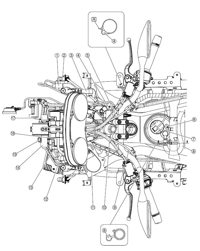
- Radiator fan motor relay
- Starting circuit cut-off relay
- Headlight relay
- Right handlebar switch lead
- Front brake hose
- Fuel pump coupler
- Fuel sender coupler
- Fuel hose
- Left handlebar switch lead
- Rear brake hose
- ECU (engine control unit)
- Positive battery lead
- Negative battery lead
- Fuse box 1
- Fuse box 2
- Battery
- Turn signal/hazard relay
- Point the end of the plastic locking tie to the left, and then cut off the excess end of the tie to 0-5 mm (0-0.20 in).
Throttle body (top view)
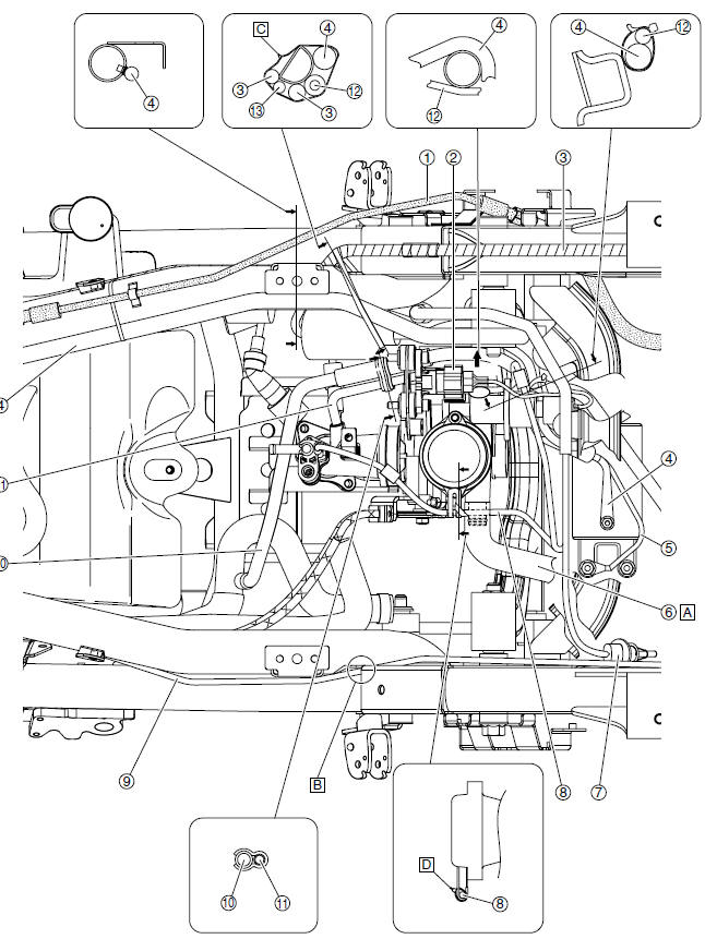
- Rear brake pipe
- Intake air pressure sensor coupler
- Wire harness
- Starter motor lead
- Ground lead
- Breather hose (air filter case to throttle body)
- Intake air temperature sensor coupler
- Fuel injector lead
- Seat lock cable
- Cylinder head breather hose
- Intake air pressure sensor hose
- Crankshaft position sensor/stator assembly lead
- O2 sensor lead
- Connect the breather hose (air filter case to throttle body) to the air filter case, making sure to turn the white paint marks on the hose upward.
- Route the seat lock cable to the inside of the frame.
- Point the end of the plastic locking tie to the right, and then cut off the excess end of the tie to 0-5 mm (0-0.20 in).
- Fasten the fuel injector lead at the white tape with a plastic locking tie. Point the end of the plastic locking tie upward, and then cut off the excess end of the tie to 0-5 mm (0-0.20 in).
Tail/brake light (top view)
- Wire harness
- Rear brake hose
- License plate light lead
- Right tail/brake light assembly coupler
- Left tail/brake light assembly coupler
- Seat lock cable
- Cylinder head breather hose
- Intake air temperature sensor coupler
- Point the end of the plastic locking tie to the right, and then cut off the excess end of the tie to 0-5 mm (0-0.20 in).
- Route the license plate light lead between the water guard and the license plate light bracket.
See also:
 Yamaha XMAX YP125R - Service manual > Cooling system diagrams
Coolant reservoir Coolant reservoir hose Radiator cap Radiator filler hose Radiator Radiator inlet hose Radiator outlet hose


