 Yamaha XMAX YP125R - Service manual > Cooling system diagrams
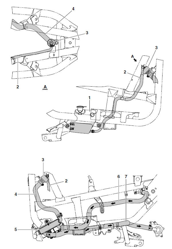
- Coolant reservoir
- Coolant reservoir hose
- Radiator cap
- Radiator filler hose
- Radiator
- Radiator inlet hose
- Radiator outlet hose
Cable routing (YP250R)
Battery (front view)
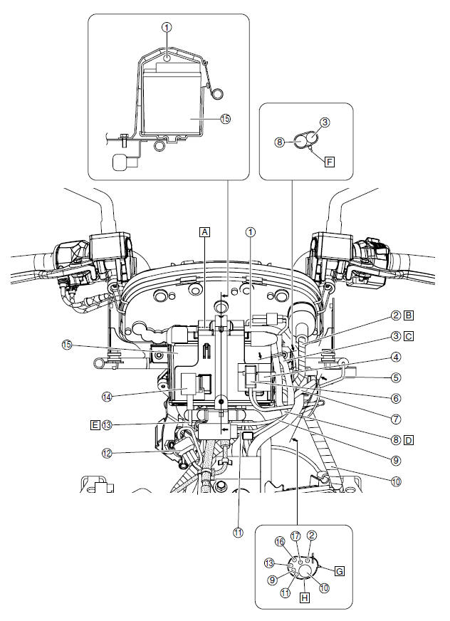
- Positive battery lead
- Meter assembly lead
- Self-diagnosis signal lead
- Fuse box 1
- Air temperature sensor lead
- Fuse box 2
- Starter relay lead
- Negative battery lead
- Headlight lead
- Wire harness
- Lean angle sensor lead
- Speed sensor coupler
- Turn signal/hazard relay lead
- Turn signal/hazard relay
- Battery
- Fuse box 2 lead
- Fuse box 1 lead
- Route the positive battery lead under the battery cover.
- Route the meter assembly lead to the front of the starter relay.
- Route the self-diagnosis signal lead along the negative battery lead.
- Route the negative battery lead to the rear of the turn signal/hazard relay lead, lean angle sensor lead, and headlight lead.
- Route the turn signal/hazard relay lead to the rear of the lean angle sensor.
- Point the end of the plastic locking tie forward, and then cut off the excess end of the tie to 0-5 mm (0-0.20 in).
- Point the end of the plastic locking tie upward, and then cut off the excess end of the tie to 0-5 mm (0-0.20 in).
- Fasten the wire harness and the other leads with a plastic locking tie, making sure to align the tie with the white tape on the harness.
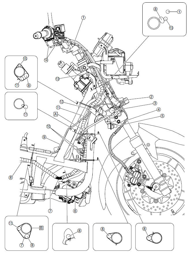
Front fork (front view)
- Speed sensor lead
- Front brake hose
- Rectifier/regulator
- Left front turn signal light coupler
- Wire harness
- Horn
- Right front turn signal light coupler
- Point the end of the plastic locking tie forward, and then cut off the excess end of the tie to 0-5 mm (0-0.20 in).
Front brake hose (right side view)
- Front brake hose
- Radiator fan motor relay
- Starting circuit cut-off relay
- Speed sensor lead
- Right front turn signal light
- Radiator fan motor
- Radiator fan motor lead
- Wire harness
- Rear brake pipe
- Horn leads
- Starter motor lead
- Headlight relay
- Rear brake hose
- Throttle cables
- Main switch/immobilizer unit lead
- Position the plastic locking tie above the frame cross member.
- Point the end of the plastic locking tie to the right, and then cut off the excess end of the tie to 0-5 mm (0-0.20 in).
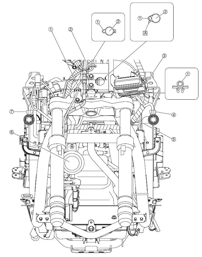
Engine (right side view)
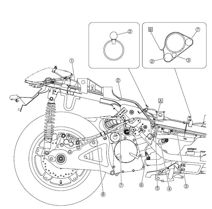
- Seat lock cable
- Wire harness
- Ignition coil lead
- Spark plug cap
- Coolant temperature sensor lead
- O2 sensor
- Starter motor lead
- Rear brake hose
- Fasten the wire harness, starter motor lead, crankshaft position sensor/stator assembly lead, and O2 sensor lead with a plastic locking tie.
- Point the end of the plastic locking tie to the right, and then cut off the excess end of the tie to 0-5 mm (0-0.20 in).
Throttle cables (left side view)
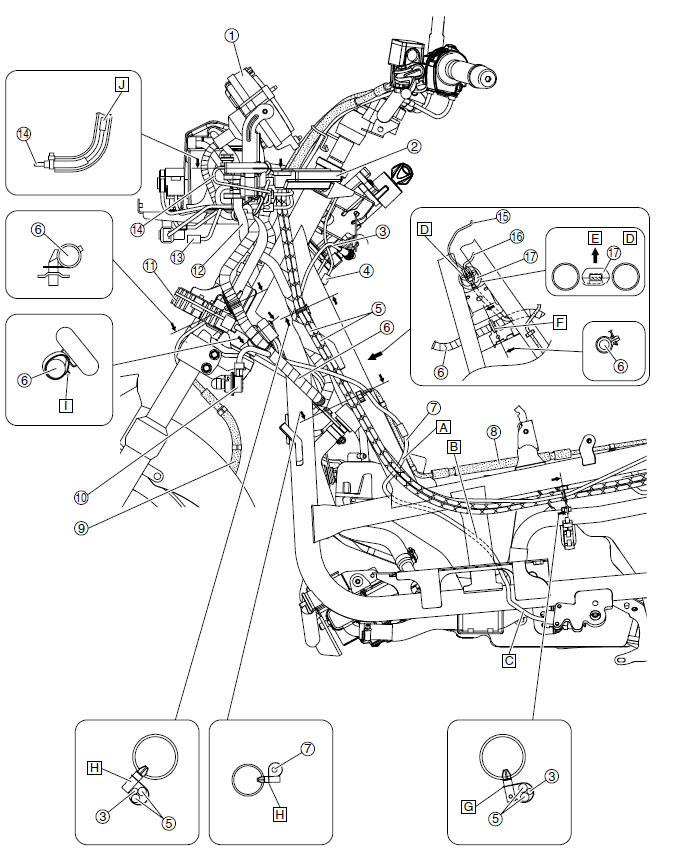
- Meter assembly
- ECU (engine control unit)
- Seat lock cable
- Immobilizer unit coupler
- Throttle cables
- Wire harness
- Sidestand switch lead
- Rear brake hose
- Front brake hose
- Left front turn signal light lead
- Rectifier/regulator
- Starter motor lead
- Headlight coupler
- Air temperature sensor lead
- Immobilizer unit lead
- Main switch lead
- Connector cover
- Route the sidestand switch lead to the outside of the rear brake pipe.
- Route the sidestand switch lead to the inside of the frame.
- Route the sidestand switch lead to the outside of the frame.
- Position the connector cover as shown in the illustration.
- Forward
- Fasten the wire harness at the white tape with the holder.
- Point the end of the plastic locking tie to the right, and then cut off the excess end of the tie to 0-5 mm (0-0.20 in).
- Point the end of the plastic locking tie forward.
- Point the end of the plastic locking tie to the left, and then cut off the excess end of the tie to 0-5 mm (0-0.20 in).
- Install the air temperature sensor so that there is some slack in the air temperature sensor lead.
See also:
 Yamaha XMAX YP125R - Service manual > Engine (left side view)
Wire harness Intake air temperature sensor Seat lock cable Left tail/brake light assembly Point the end of the plastic locking tie to the left, and then cut off the excess end of the tie to 0-5 mm (0-0.20 in).
Yamaha XMAX YP125R - Service manual > Engine (left side view)
Wire harness Intake air temperature sensor Seat lock cable Left tail/brake light assembly Safety protector O2 sensor Spark plug cap Route the left tail/brake light assembly lead and right tail/brake light assembly lead over the safety protector. Point the end of the plastic locking tie to the left, and then cut off the excess end of the tie to 0-5 mm (0-0.20 in).


