 Yamaha XMAX YP125R - Service manual > Engine (left side view)
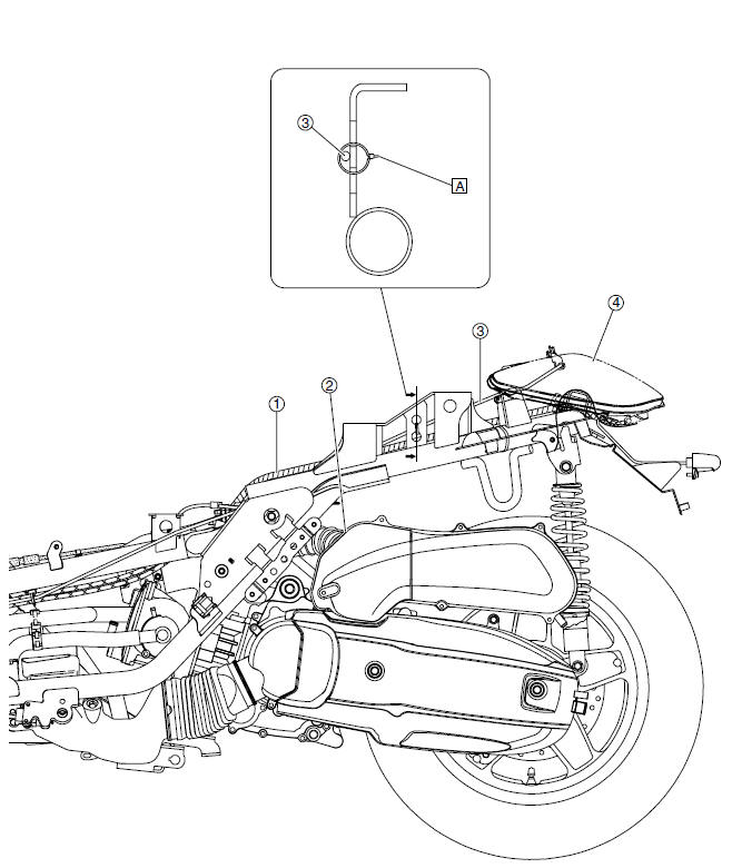
- Wire harness
- Intake air temperature sensor
- Seat lock cable
- Left tail/brake light assembly
- Point the end of the plastic locking tie to the left, and then cut off the excess end of the tie to 0-5 mm (0-0.20 in).
Handlebar (top view)
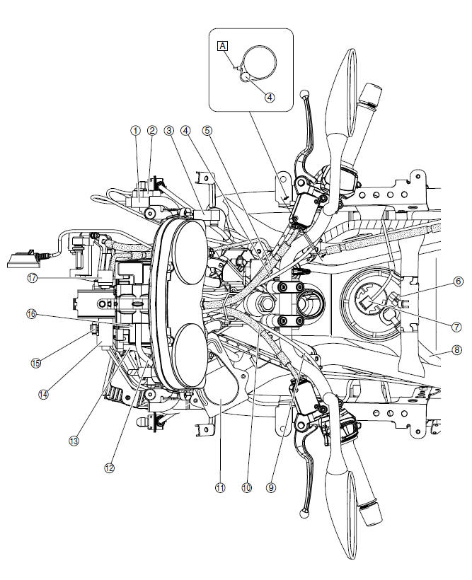
- Radiator fan motor relay
- Starting circuit cut-off relay
- Headlight relay
- Right handlebar switch lead
- Front brake hose
- Fuel pump coupler
- Fuel sender coupler
- Fuel hose
- Left handlebar switch lead
- Rear brake hose
- ECU (engine control unit)
- Positive battery lead
- Negative battery lead
- Fuse box 1
- Fuse box 2
- Battery
- Turn signal/hazard relay
- Point the end of the plastic locking tie to the left, and then cut off the excess end of the tie to 0-5 mm (0-0.20 in).
Throttle body (top view)
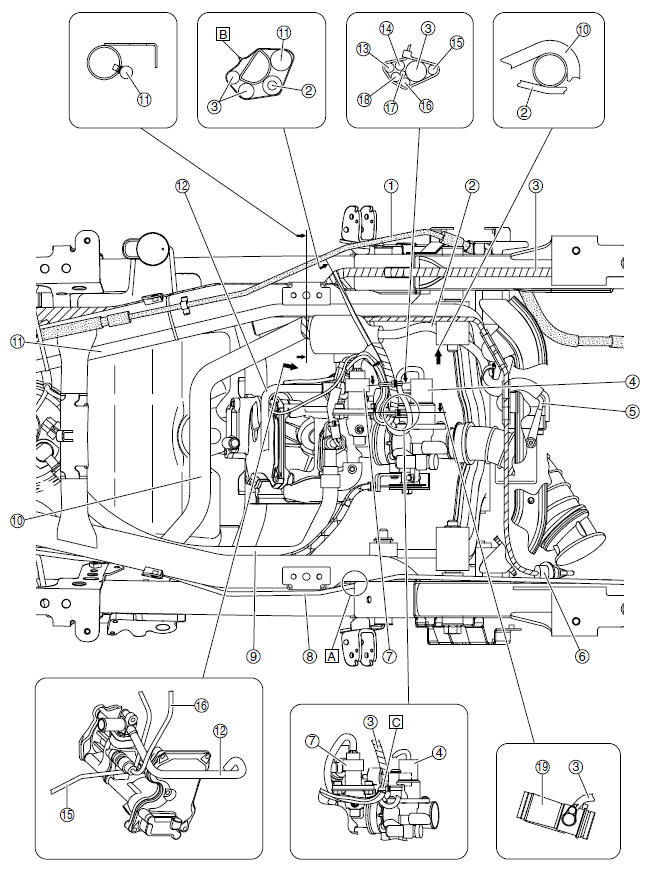
- Rear brake pipe
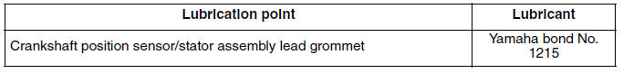
- Crankshaft position sensor/stator assembly lead
- Wire harness
- ISC (idle speed control) unit coupler
- Ground lead
- Intake air temperature sensor coupler
- Intake air pressure sensor coupler
- Seat lock cable
- Fuel injector assembly
- Radiator inlet hose
- Starter motor lead
- Thermostat inlet hose
- Intake air pressure lead
- Fuel injector lead
- Throttle position sensor lead
- Coolant temperature sensor lead
- ISC (idle speed control) unit lead
- O2 sensor lead
- Throttle body
- Route the seat lock cable to the inside of the frame.
- Point the end of the plastic locking tie to the right, and then cut off the excess end of the tie to 0-5 mm (0-0.20 in).
- Fasten the wire harness at the white tape with a plastic locking tie. Cut off the excess end of the tie to 0-5 mm (0-0.20 in).
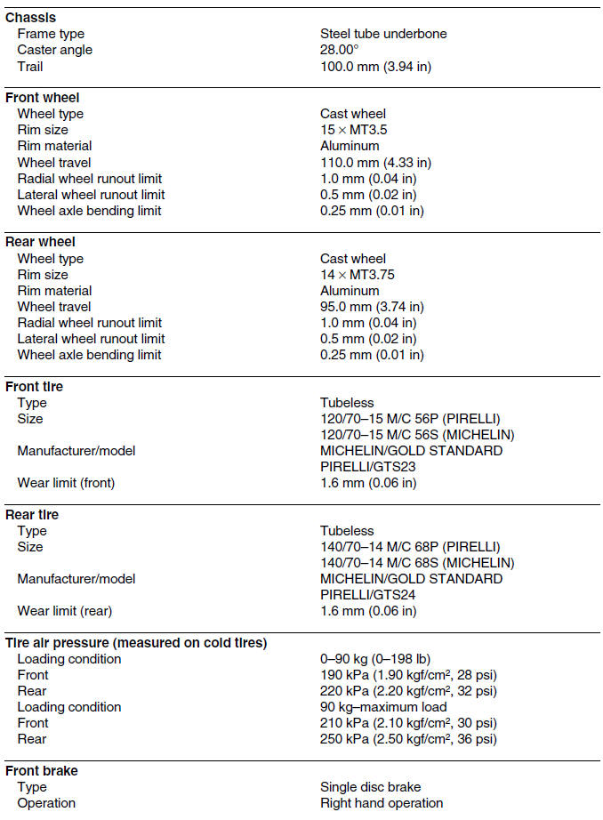
General specifications (YP250R)
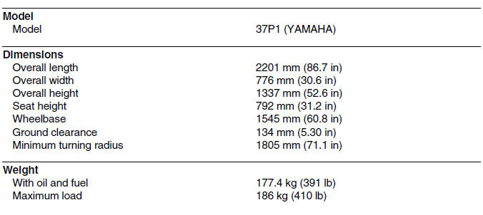
Engine specifications (YP250R)
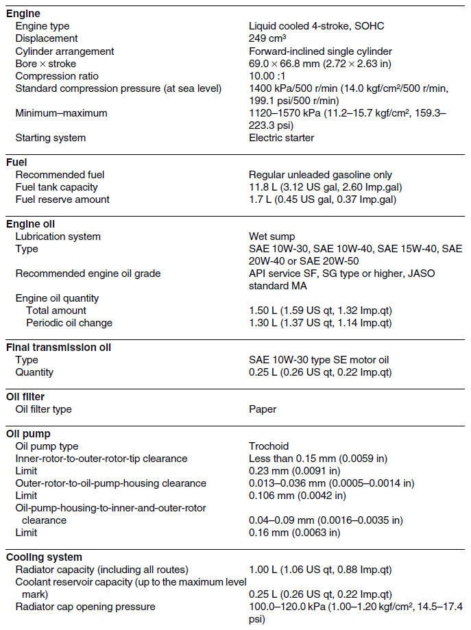
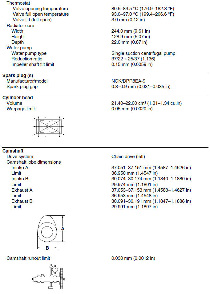
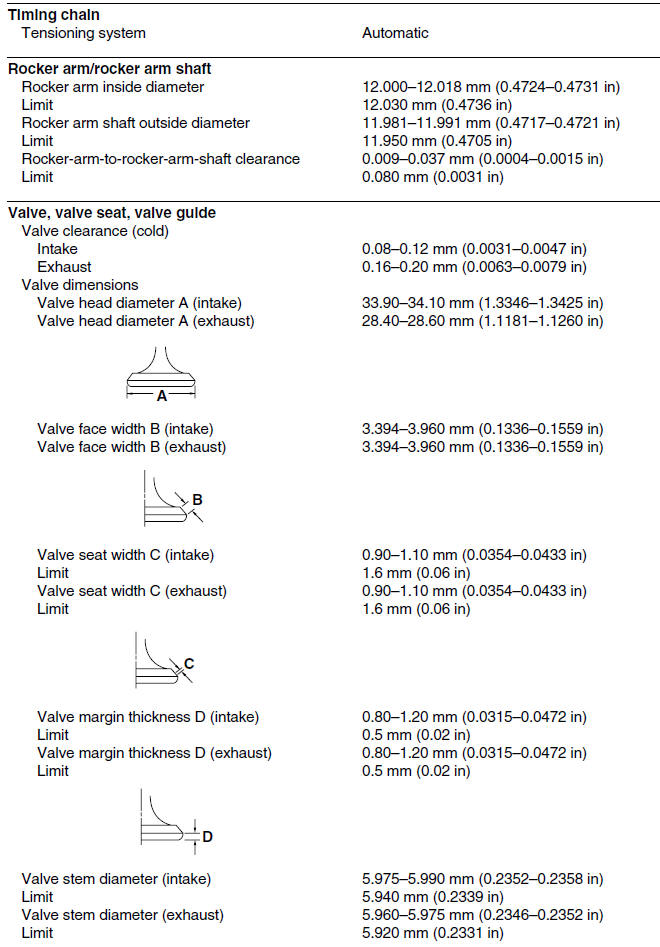
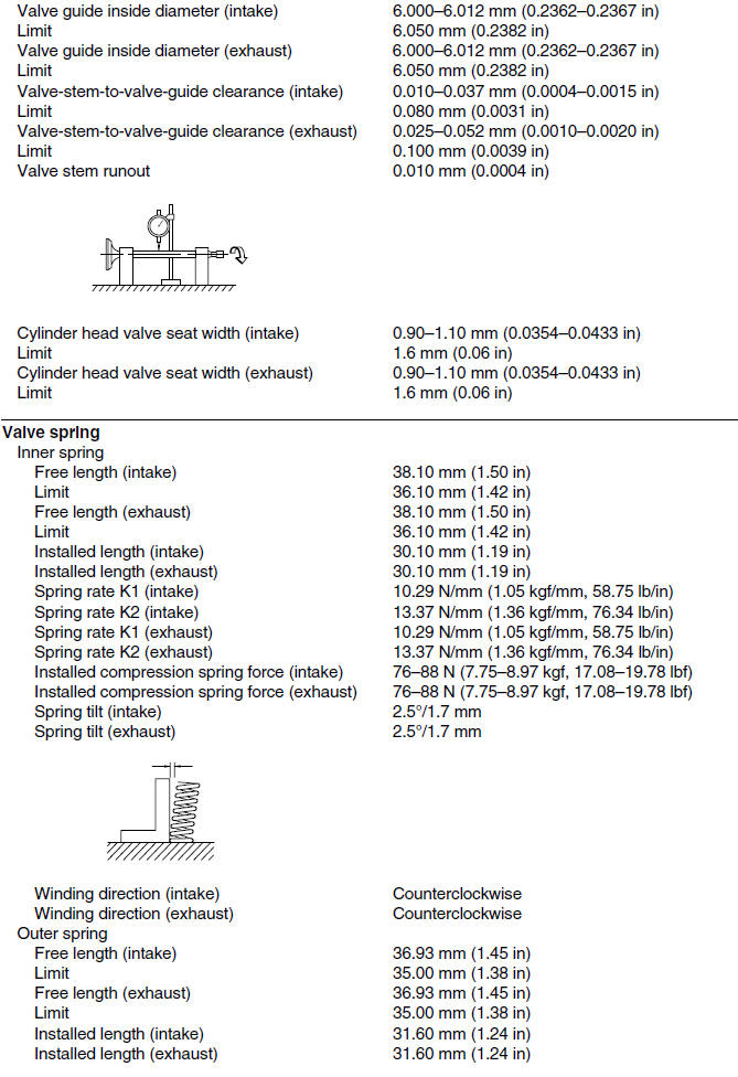
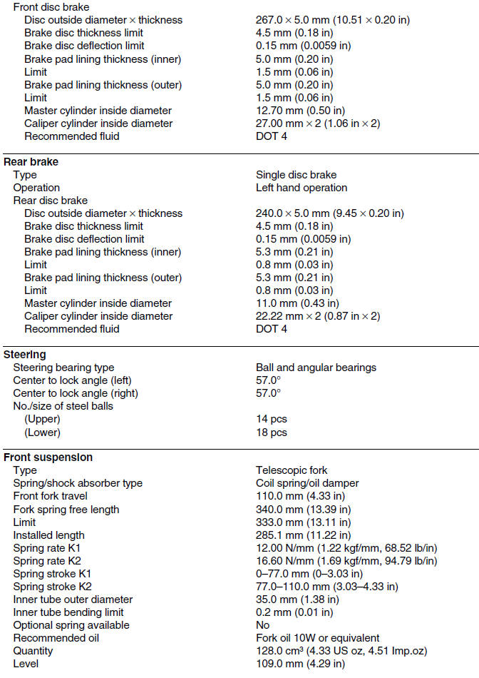
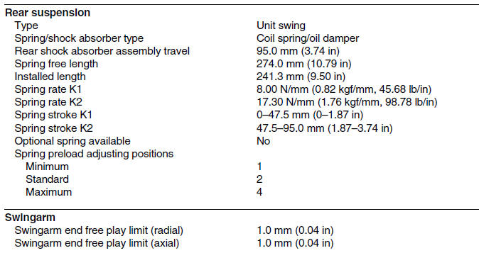
Chassis specifications (YP250R)
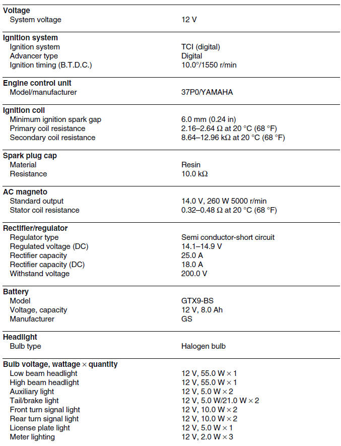
Electrical specifications (YP250R)
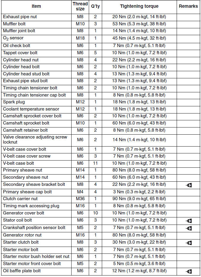
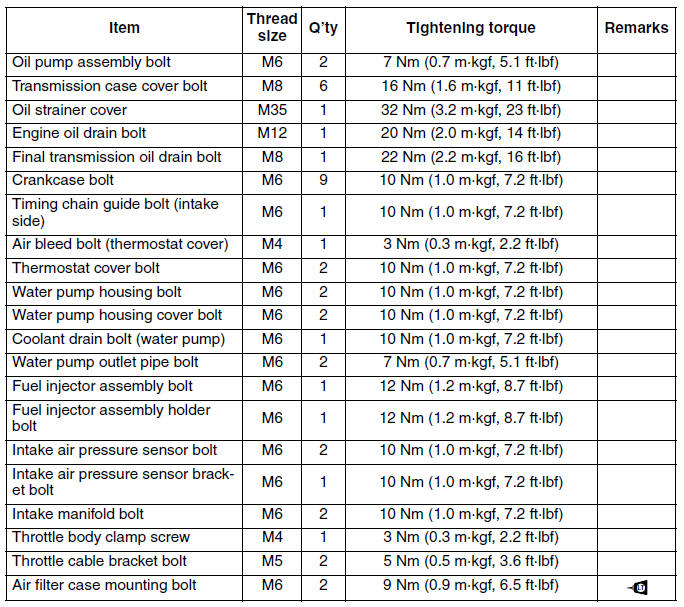
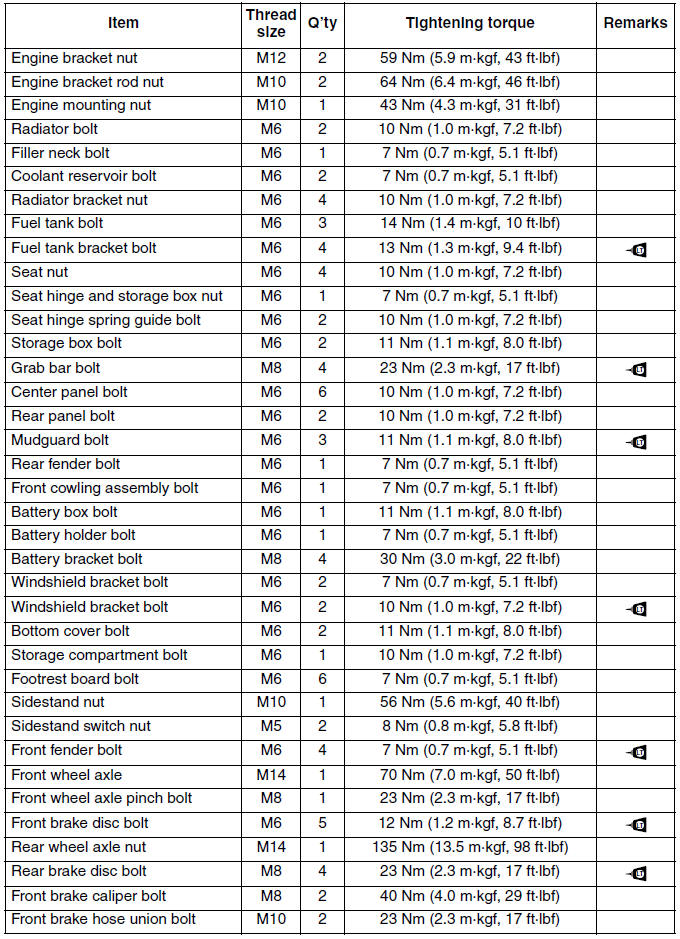
Tightening torques (YP250R)
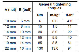
GENERAL TIGHTENING TORQUE SPECIFICATIONS
This chart specifies tightening torques for standard fasteners with a standard ISO thread pitch.
Tightening torque specifications for special components or assemblies are provided for each chapter of this manual. To avoid warpage, tighten multi-fastener assemblies in a crisscross pattern and progressive stages until the specified tightening torque is reached. Unless otherwise specified, tightening torque specifications require clean, dry threads. Components should be at room temperature.
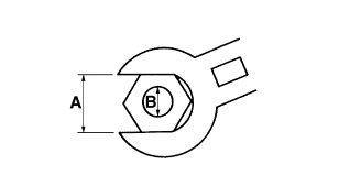
- Distance between flats
- Outside thread diameter
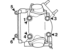
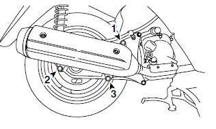
Engine tightening torques
Cylinder head tightening sequence
Muffler tightening sequence
Chassis tightening torques

TIP
Lower ring nut
1. Tighten the lower ring nut 38 Nm (3.8 m*kgf, 27 ft*lbf) with a torque wrench and the steering nut wrench, and then loosen the nut 1/4 turn.
2. Tighten the lower ring nut 22 Nm (2.2 m*kgf, 16 ft*lbf) with a torque wrench and the steering nut wrench.
3. Install the rubber washer and the center ring nut.
4. Finger tighten the center ring nut, align the slots of both ring nuts, and then install the lock washer.
5. Hold the lower and center ring nuts, and then tighten the upper ring nut 75 Nm (7.5 m*kgf, 54 ft*lbf) with a torque wrench and the steering nut wrench.
TIP
Swingarm mounting bolt
1. Temporarily install the rear wheel axle nut "1".
2. Temporarily install the swingarm mounting bolt (upper side) "2", then the swingarm mounting bolt (lower side) "3".
3. Tighten the rear wheel axle nut to 135 Nm (13.5 m*kgf, 98 ft*lbf).
4. Tighten the swingarm mounting bolt (upper side), then the swingarm mounting bolt (lower side) to 59 Nm (5.9 m*kgf, 43 ft*lbf).
Swingarm tightening sequence
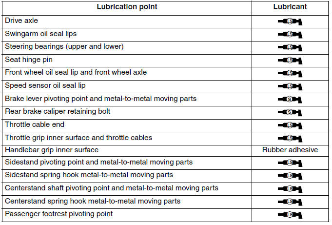
Lubrication points and lubricant types (YP250R)
ENGINE
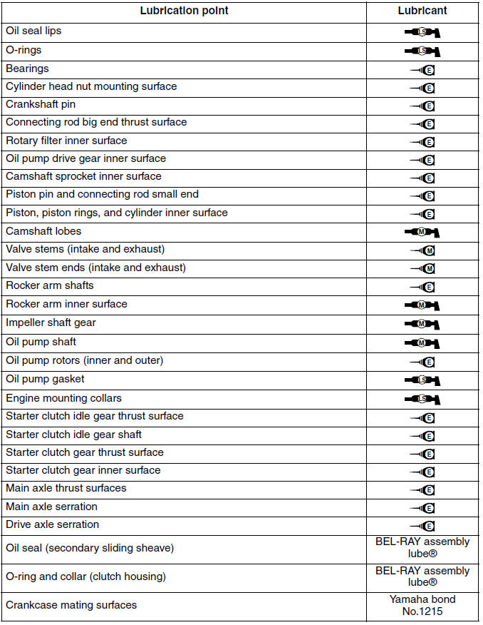
Chassis
See also:
 Yamaha XMAX YP125R - Service manual > Front brake hose (right side view)
Front brake hose Radiator fan motor relay Starting circuit cut-off relay Speed sensor lead Right front turn signal light Radiator fan motor Radiator fan motor lead Wire harness Rear brake pipe Horn leads Starter motor lead Headlight relay Rear brake hose Throttle cables Position the plastic locking tie above the frame cross member. Point the end of the plastic locking tie to the right, and then cut off the excess end of the tie to 0-5 mm (0-0.20 in). Point the end of the plastic locking tie forward, and then cut off the excess end of the tie to 0-5 mm (0-0.20 in).
Yamaha XMAX YP125R - Service manual > Cooling system diagrams
Coolant reservoir Coolant reservoir hose Radiator cap Radiator filler hose Radiator Radiator inlet hose Radiator outlet hose


