 Yamaha XMAX YP125R - Service manual > Front brake hose (right side view)
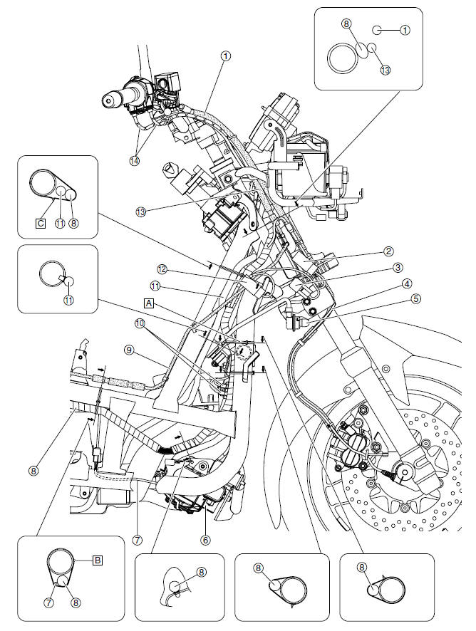
- Front brake hose
- Radiator fan motor relay
- Starting circuit cut-off relay
- Speed sensor lead
- Right front turn signal light
- Radiator fan motor
- Radiator fan motor lead
- Wire harness
- Rear brake pipe
- Horn leads
- Starter motor lead
- Headlight relay
- Rear brake hose
- Throttle cables
- Position the plastic locking tie above the frame cross member.
- Point the end of the plastic locking tie to the right, and then cut off the excess end of the tie to 0-5 mm (0-0.20 in).
- Point the end of the plastic locking tie forward, and then cut off the excess end of the tie to 0-5 mm (0-0.20 in).
Engine (right side view)
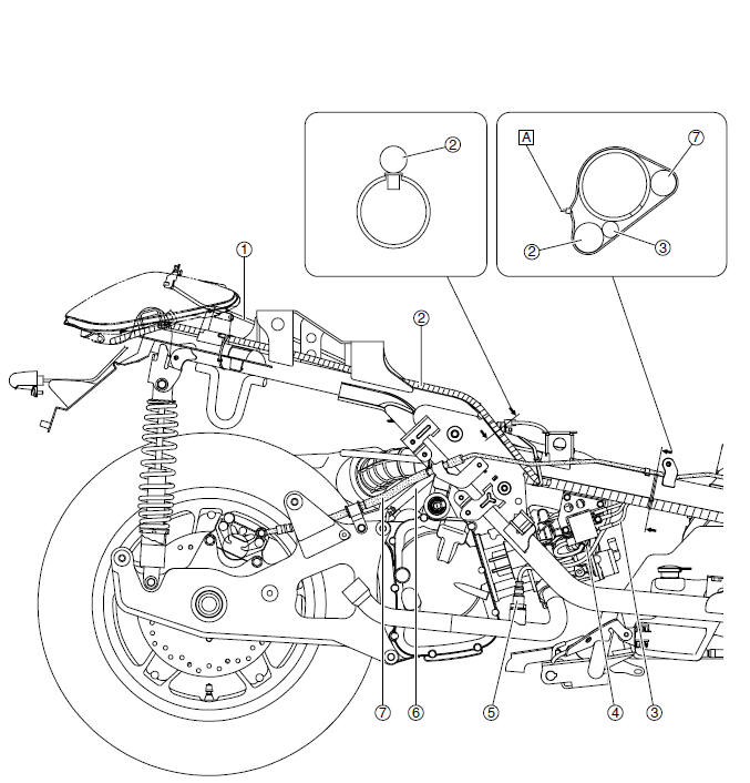
- Seat lock cable
- Wire harness
- Ignition coil lead
- Spark plug cap
- O2 sensor
- Starter motor lead
- Rear brake hose
- Point the end of the plastic locking tie to the right, and then cut off the excess end of the tie to 0-5 mm (0-0.20 in).
Throttle cables (left side view)
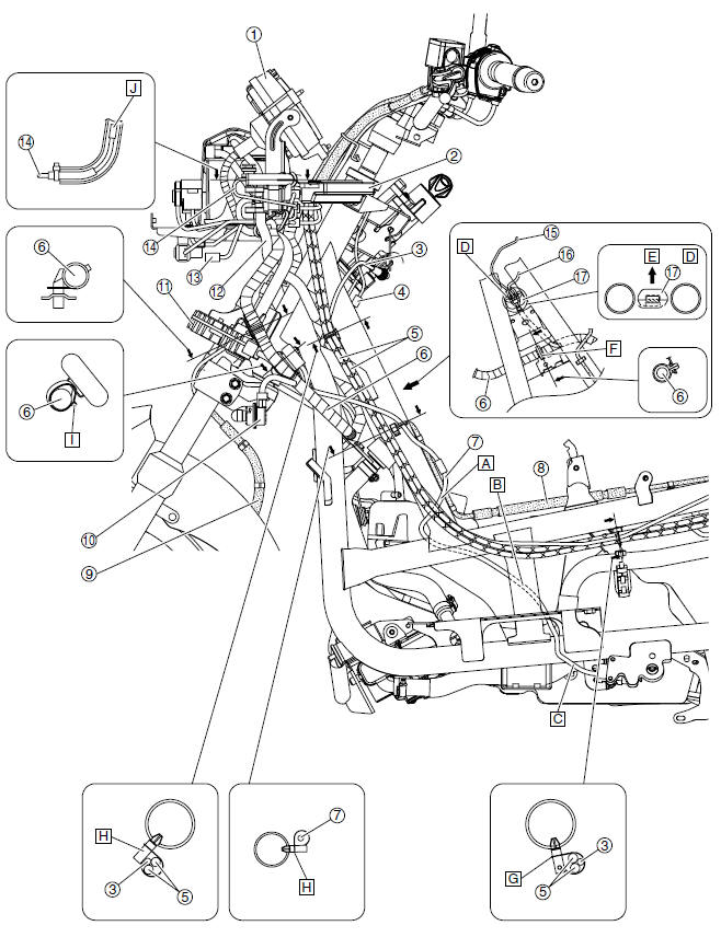
- Meter assembly
- ECU (engine control unit)
- Seat lock cable
- Immobilizer unit coupler
- Throttle cables
- Wire harness
- Sidestand switch lead
- Rear brake hose
- Front brake hose
- Left front turn signal light lead
- Rectifier/regulator
- Starter motor lead
- Headlight coupler
- Air temperature sensor lead
- Immobilizer unit lead
- Main switch lead
- Connector cover
- Route the sidestand switch lead to the outside of the rear brake pipe.
- Route the sidestand switch lead to the inside of the frame.
- Route the sidestand switch lead to the outside of the frame.
- Position the connector cover as shown in the illustration.
- Forward
- Fasten the wire harness at the white tape with the holder.
- Point the end of the plastic locking tie to the right, and then cut off the excess end of the tie to 0-5 mm (0-0.20 in).
- Point the end of the plastic locking tie forward
- Point the end of the plastic locking tie to the left, and then cut off the excess end of the tie to 0-5 mm (0-0.20 in).
- Install the air temperature sensor so that there is some slack in the air temperature sensor lead.
See also:
 Yamaha XMAX YP125R - Service manual > Tightening torques
General tightening torque specifications This chart specifies tightening torques for standard fasteners with a standard ISO thread pitch. Tightening torque specifications for special components or assemblies are provided for each chapter of this manual. To avoid warpage, tighten multi-fastener assemblies in a crisscross pattern and progressive stages until the specified tightening torque is reached. Unless otherwise specified, tightening torque specifications require clean, dry threads. Components should be at room temperature. Distance between flats Outside thread diameter
Yamaha XMAX YP125R - Service manual > Engine (left side view)
Wire harness Intake air temperature sensor Seat lock cable Left tail/brake light assembly Point the end of the plastic locking tie to the left, and then cut off the excess end of the tie to 0-5 mm (0-0.20 in).


