 Vespa GTS Super 300 ie - Service manual > Front brake pump
Removal
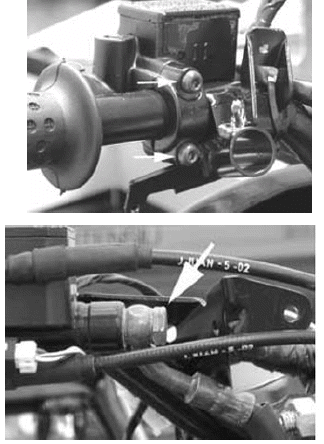
- Remove the rear handlebar cover.
- Remove the two screws fixing the brake pump to the handlebar indicated in the photograph
- Remove the oil pipe joint from the pump
- Remove the connector to the stop light switch
Overhaul
Proceed as follows:
1) Remove the brake lever by loosening the retaining screw; open the cover (2) and take out the diaphragm (3);
2) remove the cap (4) and take out the internal parts in order;
3) Check that:
- The pump body shows no signs of internal damage or corrosion;
- The plunger shows no sign of damage or abnormal wear;
- The piston return spring is in good condition.
CAUTION
ALL THE SEALS AND GASKETS MUST BE REPLACED EVERY TIME THE PUMP IS SERVICED.
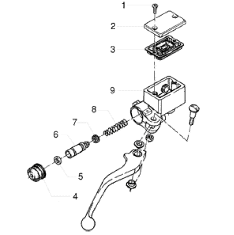
- Reservoir cap screw
- Reservoir cap.
- Diaphragm.
- Bellows.
- Sealing ring
- Piston.
- Gasket.
- Spring.
- Tank
Refitting
To refit, carry out the removal operations but in reverse order, observing the specified torques.
Locking torques (N*m)
Oil pipe joint to the pump: 20 - 25 Brake pump fixing screws to the
handlebar: 7 to 10 Nm
See also:
 Vespa GTS Super 300 ie - Service manual > Fill
Rear - combined Remove the rubber cap from the bleed screw. Insert a rubber pipe in the bleed screw to permit the brake fluid to be recovered. With the left-had brake lever, load the system and bring it up to the required pressure. Keeping the left-hand brake lever pulled, loosen the bleed screw to permit the air in the system to escape. Then tighten the bleed screw Repeat the operation until only brake fluid comes out of the rubber pipe. Remove the fluid recovery pipe and refit the rubber cap over the bleed screw. Top up the brake fluid to the right level in the reservoir.
Vespa GTS Super 300 ie - Service manual > Cooling System
Circuit diagram


