 Yamaha XMAX YP125R - Service manual > Fuel injection system
Circuit diagram
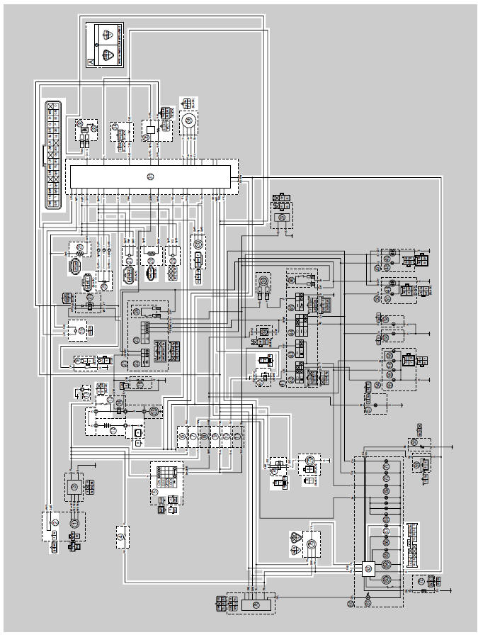
2. Crankshaft position sensor
4. Backup fuse (immobilizer unit and meter assembly)
5. Main switch
6. ECU fuse
7. Radiator fan motor fuse
9. Ignition fuse
10. Headlight fuse
12.Battery
13.Main fuse
17. Frame ground
18. Sidestand switch
19. Fuel pump
25.Coolant temperature sensor
26.Throttle position sensor
27. Intake air pressure sensor
28. Intake air temperature sensor
29. Lean angle sensor
30. Speed sensor
31. ECU (engine control unit)
32. Ignition coil
33. Spark plug
34. Fuel injector
35. O2 sensor
36. ISC (idle speed control) unit
40. Headlight relay
62. Multifunction meter
67. Engine trouble warning light
73. Radiator fan motor
74. Radiator fan motor relay
75. Self-diagnosis signal coupler
A. YP250R only
Ecu self-diagnostic function
The ECU is equipped with a self-diagnostic function in order to ensure that the fuel injection system is operating normally. If this function detects a malfunction in the system, it immediately operates the engine under substitute characteristics and illuminates the engine trouble warning light to alert the rider that a malfunction has occurred in the system. Once a malfunction has been detected, a fault code is stored in the memory of the ECU.
- To inform the rider that the fuel injection system is not functioning, the engine trouble warning light flashes when the start switch is being pushed to start the engine.
- If a malfunction is detected in the system by the self-diagnostic function, the ECU provides an appropriate substitute characteristic operation, and alerts the rider of the detected malfunction by illuminating the engine trouble warning light.
- After the engine has been stopped, the lowest fault code number appears
on the odometer LCD.
Once a fault code has been displayed, it remains stored in the memory of the ECU until it is deleted.
Engine trouble warning light indication and fuel injection system operation
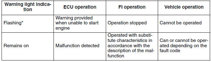
* The warning light flashes when any one of the conditions listed below is present and the start switch is pushed:
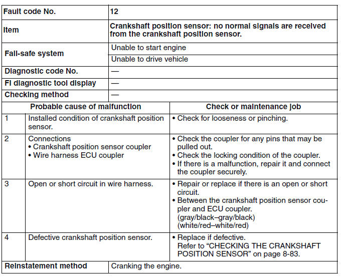
12: Crankshaft position sensor
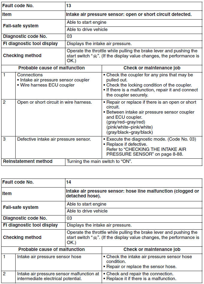
13: Intake air pressure sensor (open or short circuit)
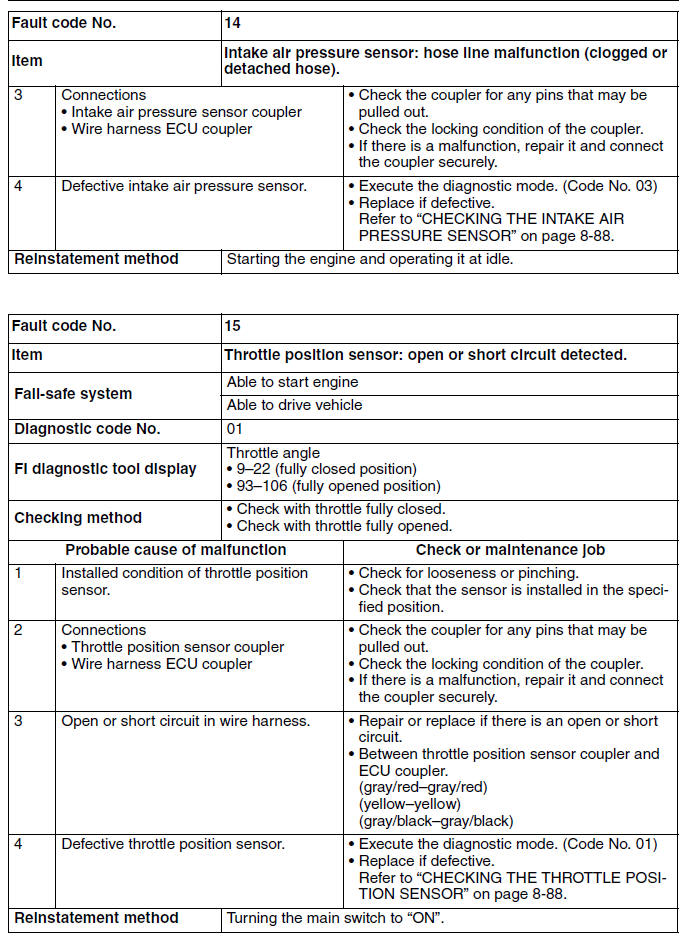
14: Intake air pressure sensor (clogged or detached hose)
15: Throttle position sensor (open or short circuit)
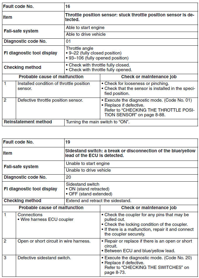
16: Throttle position sensor (stuck)
19: Blue/yellow ECU lead (broken or disconnected)
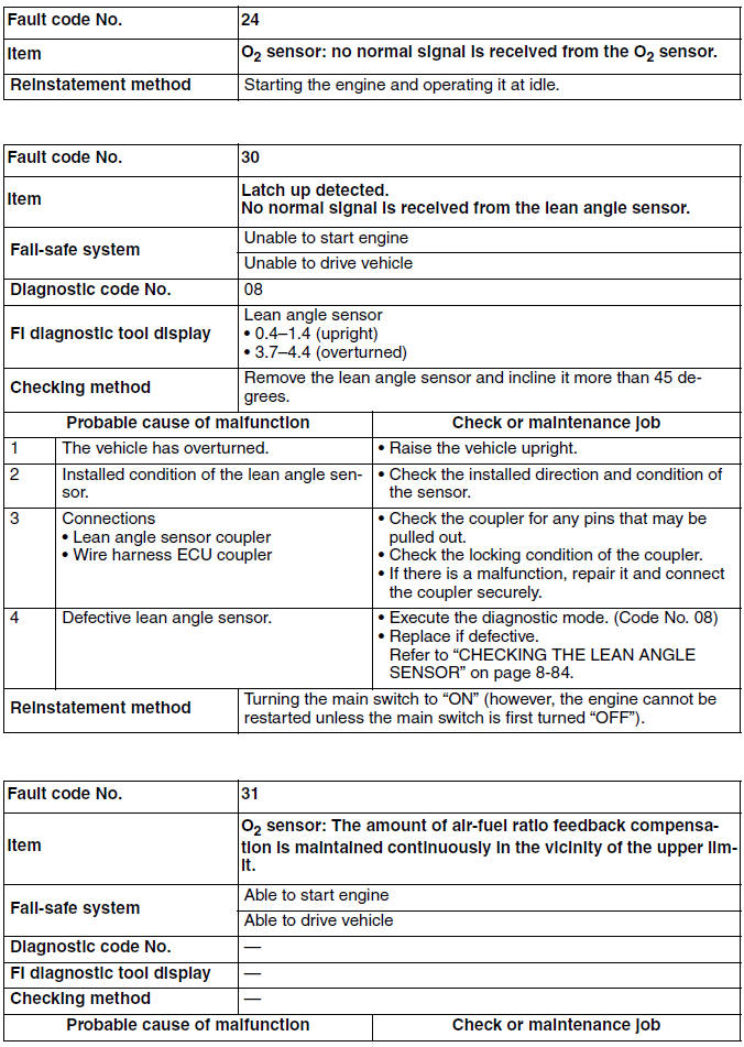
30: Lean angle sensor (latch up detected)
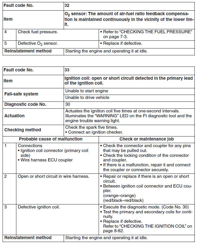
33: Faulty ignition
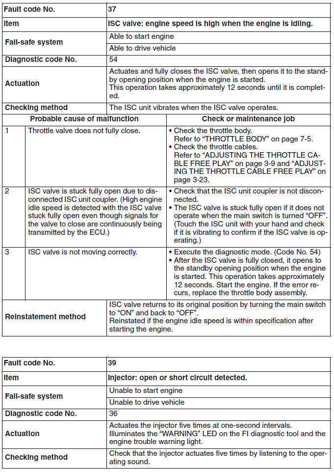
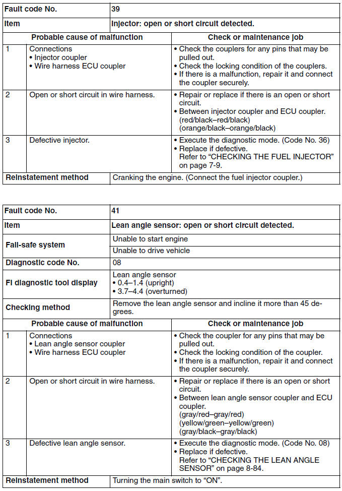
39: Fuel injector (open or short circuit)
41: Lean angle sensor (open or short circuit)
50: ECU internal malfunction (memory check error)
Checking for a defective engine trouble warning light
The engine trouble warning light comes on for 2.0 seconds after the main switch has been set to "ON" and when the start switch is being pushed. If the warning light does not come on under these conditions, the warning light bulb may be defective.
ECU detects an abnormal signal from a sensor
If the ECU detects an abnormal signal from a sensor while the vehicle is being driven, the ECU illuminates the engine trouble warning light and provides the engine with alternate operating instructions that are appropriate for the type of malfunction.
When an abnormal signal is received from a sensor, the ECU processes the specified values that are programmed for each sensor in order to provide the engine with alternate operating instructions that enable the engine to continue operating or stop operating, depending on the conditions.
Troubleshooting method
The engine operation is not normal and the engine trouble warning light comes on.
1. Check:
- Fault code number
a. Check the fault code number displayed on the meter.
b. Identify the faulty system with the fault code number.
c. Identify the probable cause of the malfunction.
2. Check and repair the probable cause of the
malfunction. 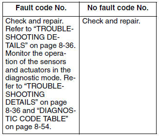
3. Perform the reinstatement action for the fuel injection system.
4. Set the main switch to "OFF", then to "ON" again, and then check that no fault code number is displayed.
TIP
If another fault code number is displayed, repeat steps (1) to (4) until no fault code number is displayed.
5. Erase the malfunction history in the diagnostic mode.
TIP
Setting the main switch to "OFF" will not erase the malfunction history.
The engine operation is not normal, but the engine trouble warning light does not come on.
1. Check the operation of the following sensors and actuators in the Diagnostic mode.
01: Throttle position sensor (throttle angle)
30: Ignition coil
36: Fuel injector
If a malfunction is detected in the sensors or actuators, repair or replace all faulty parts.
If no malfunction is detected in the sensors and actuators, check and repair the inner parts of the engine.
Diagnostic mode
It is only possible to monitor the sensor output data or check the activation of actuators by connecting the FI diagnostic tool to the vehicle and setting the diagnostic mode.
TIP
The diagnostic mode can only be set using the FI diagnostic tool. The diagnostic mode cannot be set using the meter.
 FI diagnostic tool
90890-03182
FI diagnostic tool
90890-03182
Setting the diagnostic mode
1. Set the main switch to "OFF".
2. Disconnect the self-diagnosis signal coupler, and then connect the FI diagnostic tool "1" as shown.
3. While pressing the "MODE" button, set the main switch to "ON".
TIP
- "DIAG" appears on the LCD of the FI diagnostic tool. If "CO" appears on the LCD of the FI diagnostic tool, press the "UP" button to select "DIAG".
- The "POWER" LED (green) comes on.
4. Press the "MODE" button.
TIP
The diagnostic code number "D01" appears on the LCD of the FI diagnostic tool.
5. Select the diagnostic code number corresponding to the fault code number by pressing the "UP" and "DOWN" buttons.
TIP
- The diagnostic code number appears on the LCD (01-70).
- To decrease the selected diagnostic code number, press the "DOWN" button. Press the "DOWN" button for 1 second or longer to automatically decrease the diagnostic code numbers.
- To increase the selected diagnostic code number, press the "UP" button. Press the "UP" button for 1 second or longer to automatically increase the diagnostic code numbers.
6. Check the operation of the sensor or actuator.
- Sensor operation
The data representing the operating conditions of the sensor appear on the LCD.
- Actuator operation
Press the "MODE" button.
7. Set the main switch to "OFF" to cancel the diagnostic mode.
8. Disconnect the FI diagnostic tool and connect the self-diagnosis signal coupler.
TIP
Information about each diagnostic code number is organized in this manual as follows:
- If a diagnostic code number has a corresponding fault code number, the information is shown in "TROUBLESHOOTING DETAILS".
- If a diagnostic code number does not have a corresponding fault code number, the information is shown in "DIAGNOSTIC CODE TABLE".
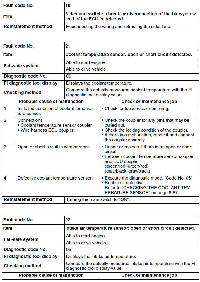
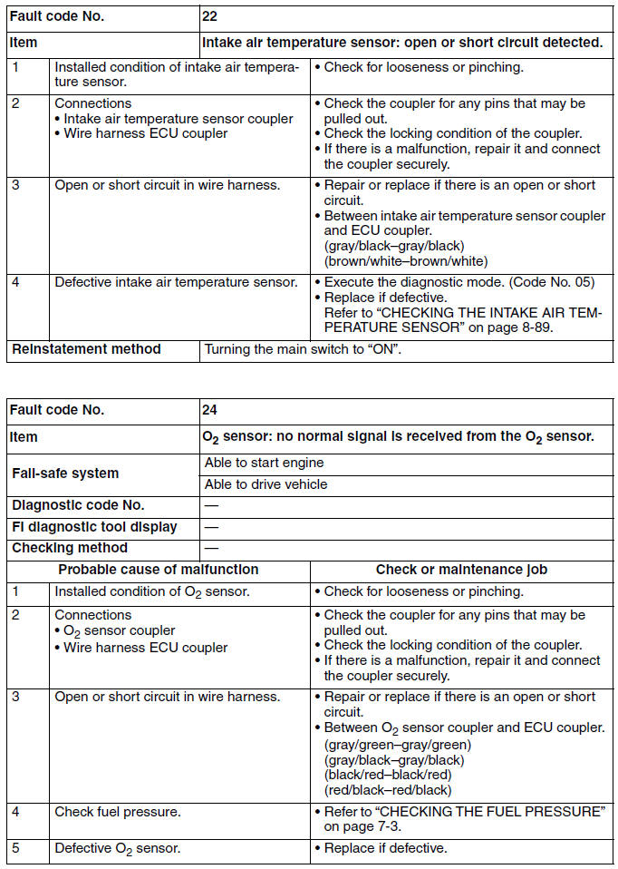
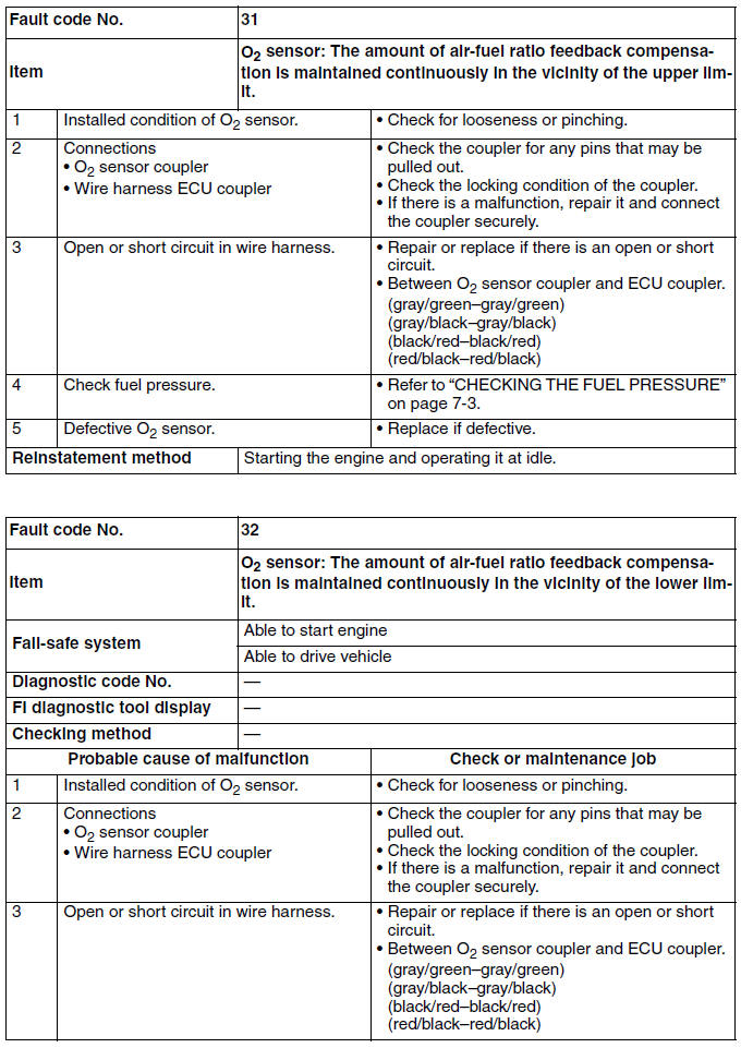
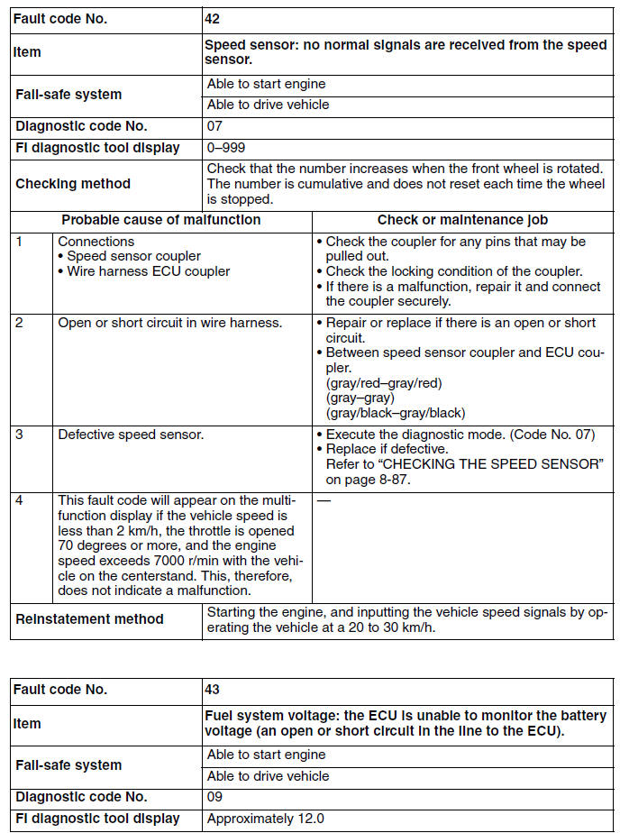
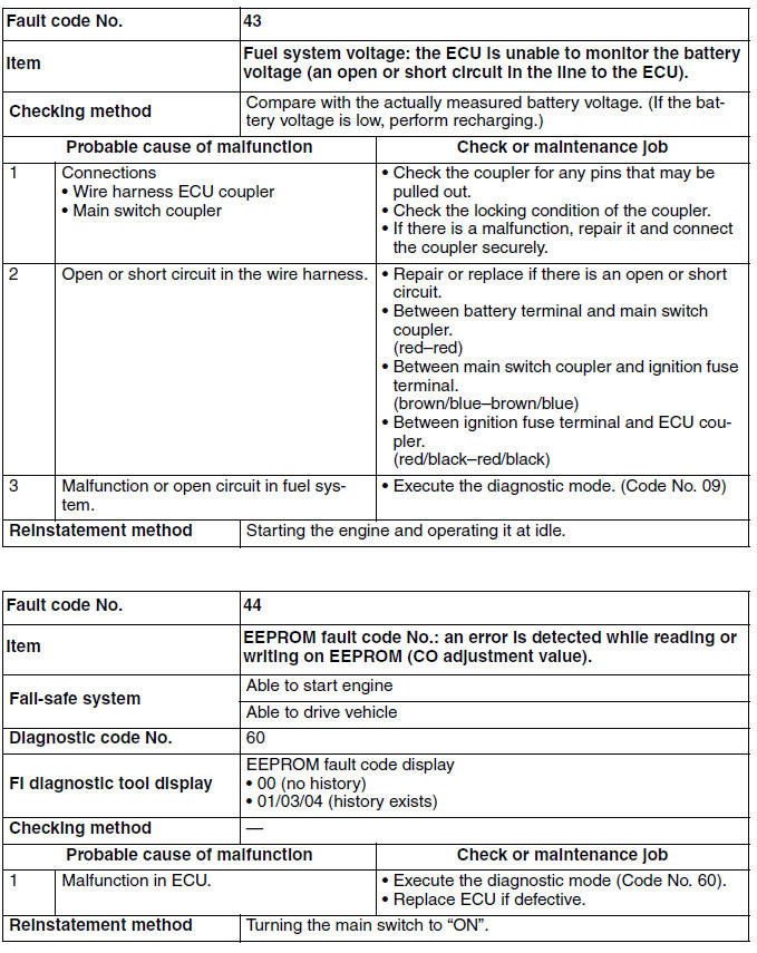
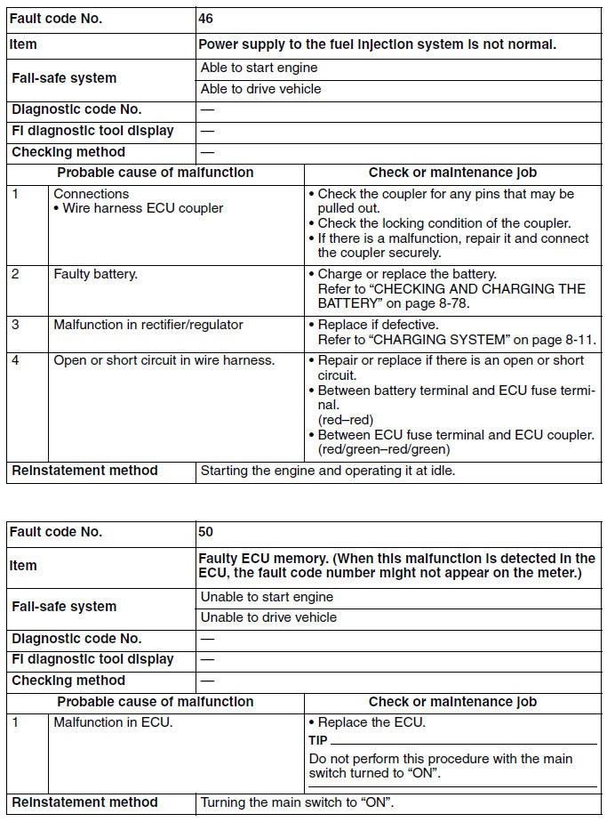
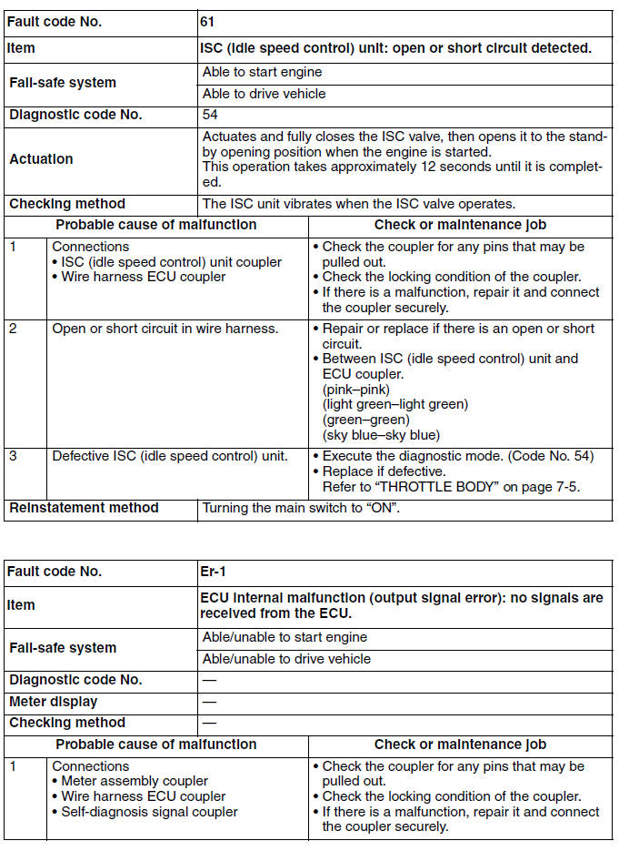
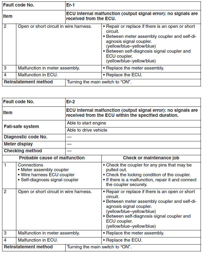
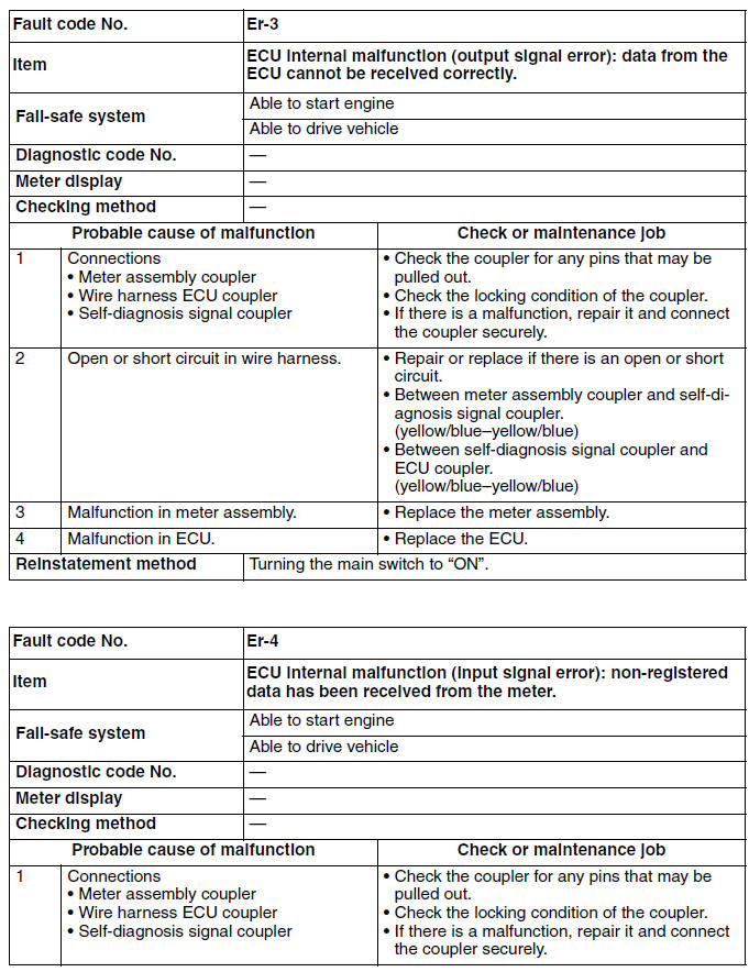
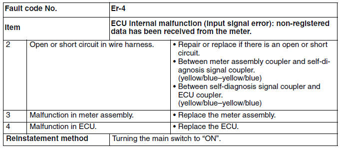
Troubleshooting details
This section describes the measures per fault code number displayed on the meter. Check and service the items or components that are the probable cause of the malfunction following the order given.
After the check and service of the malfunctioning part have been completed, reset the meter display according to the reinstatement method.
Fault code No.:
Fault code number displayed on the meter when the engine failed to work normally.
Diagnostic code No.:
Diagnostic code number to be used when the diagnostic mode is operated.
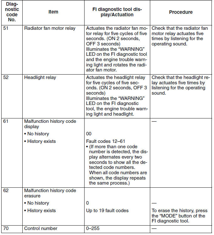
Diagnostic code table
The following tables contain information about diagnostic code numbers that do not have a corresponding fault code number. (These items are not listed in "TROUBLESHOOTING DETAILS".)
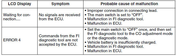
Communication error with the FI diagnostic tool
See also:
 Yamaha XMAX YP125R - Service manual > Signaling system
Circuit diagram 2. Crankshaft position sensor 5. Main switch
Yamaha XMAX YP125R - Service manual > Fuel pump system
Circuit diagram 5. Main switch 6. ECU fuse 9. Ignition fuse


