 Yamaha XMAX YP125R - Service manual > Signaling system
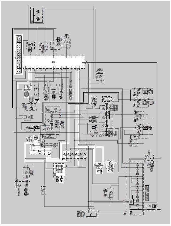
Circuit diagram
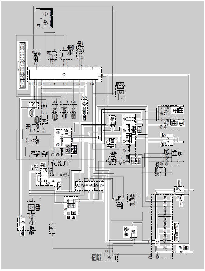
2. Crankshaft position sensor
5. Main switch
6. ECU fuse
8. Turn signal/hazard fuse
9. Ignition fuse
11. Signaling system fuse
12. Battery
13. Main fuse
17. Frame ground
23. Hazard switch
24. Front brake light switch
25.Coolant temperature sensor
30. Speed sensor
31. ECU (engine control unit)
38. Horn
39.Turn signal/hazard relay
44.Turn signal switch
45. Horn switch
46. Rear brake light switch
48. Right rear turn signal light
49. Tail/brake light
51. Left rear turn signal light
52. Right front turn signal light
53. Left front turn signal light
58. Fuel sender
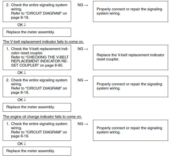
59.V-belt replacement indicator reset coupler
62. Multifunction meter
63. Speedometer
64.Tachometer
65. Engine oil change indicator
66.V-belt replacement indicator
70. Right turn signal indicator light
71. Left turn signal indicator light
72. Air temperature sensor
75. Self-diagnosis signal coupler
Troubleshooting
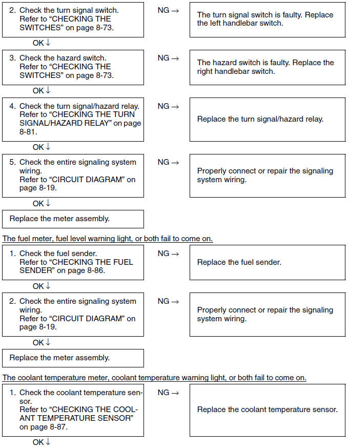
- Any of the following fail to light: turn signal lights, brake lights, warning light or indicator lights.
- The horn fails to sound.
- The fuel meter fails to operate.
- The coolant temperature meter fails to operate.
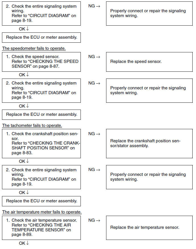
- The speedometer fails to operate.
- The tachometer fails to operate.
- The air temperature meter fails to operate.
TIP
- Before troubleshooting, remove the following part(s):
1. Storage box
2. Front cowling
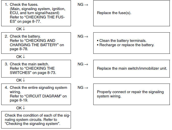
Checking the signaling system
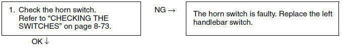
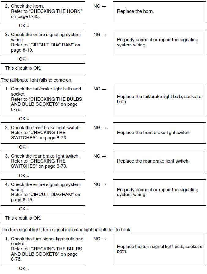
The horn fails to sound.
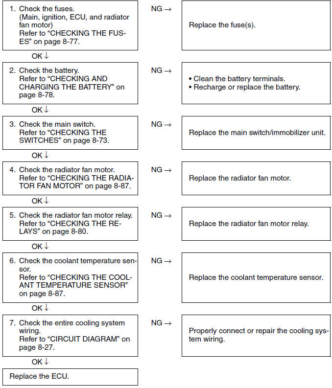
Cooling system
Circuit diagram
5. Main switch
6. ECU fuse
7. Radiator fan motor fuse
9. Ignition fuse
12.Battery
13.Main fuse
17.Frame ground
25.Coolant temperature sensor
31.ECU (engine control unit)
73.Radiator fan motor
74.Radiator fan motor relay
Troubleshooting
- The radiator fan motor fails to turn.
TIP
- Before troubleshooting, remove the following part(s):
- Storage box
- Front cowling
- Radiator cover
See also:
 Yamaha XMAX YP125R - Service manual > Ignition system
Circuit diagram 2. Crankshaft position sensor 5. Main switch
Yamaha XMAX YP125R - Service manual > Fuel injection system
Circuit diagram 2. Crankshaft position sensor 4. Backup fuse (immobilizer unit and meter assembly)


