 PIAGGIO Beverly 300ie - Service manual > Fuel tank
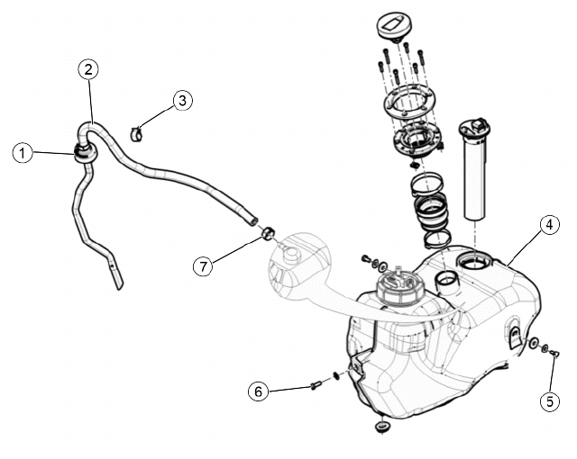
KEY:
- Safety valve
- Breather pipe
- Elastic clip
- Fuel tank
- Side fixing screws
- Front fixing screws
- Hose clamp
FUEL TANK REMOVAL:
Position the vehicle on the central stand and on a flat surface.
N.B.
THIS OPERATION SHOULD PREFERABLY BE PERFORMED WITH THE TANK EMPTY.
First remove:
- the lower side fairings;
- the footrests;
- the lower central cover;
- the leg shield back plate.
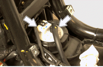
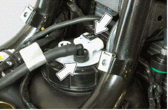
Disconnect the connector of the fuel pump and the fuel piping acting on the quick-release fitting.
WARNING
PAY ATTENTION TO THE SPILLING OF FUEL DUE TO PIPE PRESSURE.
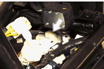
Disconnect the connector of the level indicator.
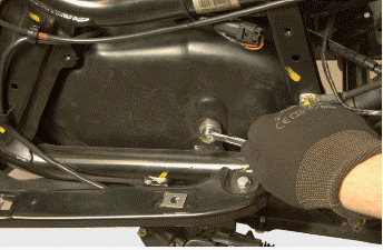
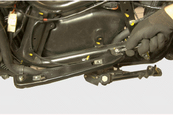
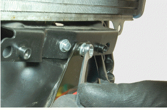
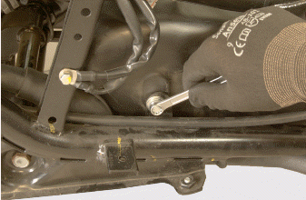
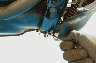
Remove the side screws fixing the tank to the frame.
Loosen the screws securing the support of the footrest to the frame and remove it.
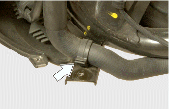
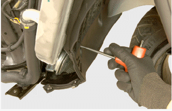
Release the coolant pipe from the front crosspiece by operating on the retaining clamp.
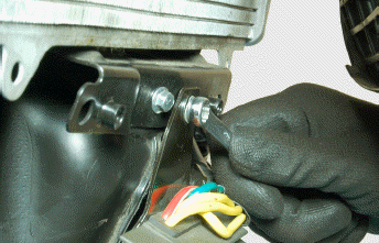
Undo the nuts locking the bracket of the voltage regulator to the front crosspiece.
Undo the fixing screws of the front crosspiece to the frame.
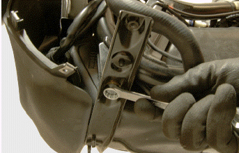
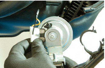
Remove the crosspiece by disconnecting the electrical connector of the horn.
From the left side, release the accelerator cables from the frame, loosening the fixing screw of the appropriate retaining clip.
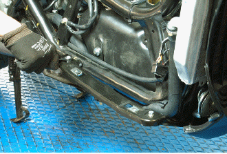
Undo the fixing screws of the rear crosspiece to the frame and remove it.
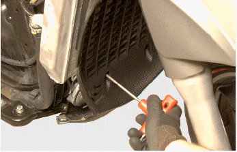
Unscrew the lower fixing screws of the front wheel housing.
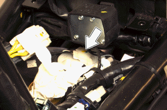
In the event that the breather pipe is present, remove its elastic clip that fastens to the frame.
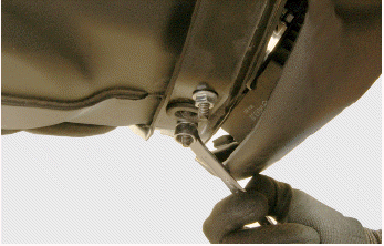
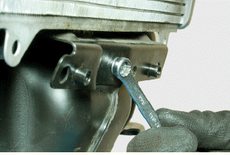
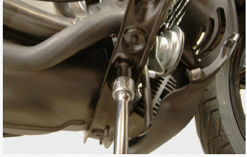
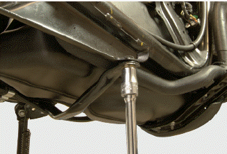
Undo the front fixing screw of the tank to the frame.
Undo the fixing screw of the voltage regulator and remove it.
Remove the tank, pulling it off from the bottom.
REMOVAL OF FUEL TANK
Fit the tank, inserting it from below.
Tighten the front fixing screw of the tank to the frame.
Locking torques (N*m)
Tank front screw - frame 8 ÷ 10.5
Tighten the side screws fixing the tank to the frame.
Locking torques (N*m)
Tank side screws - Frame 5.5 ÷ 7
Loosely tighten the fixing screw of the voltage regulator bracket to the frame.
Connect the relative electrical connection to the horn.
Fit the front crosspiece making sure that the lower pin of the tank fits perfectly in the central slot provided on the said crosspiece.
Tighten the fixing screws of the front crosspiece to the frame.
Tighten the lock nuts of the bracket of the regulator to the front crosspiece.
After tightening the fixing screw of the bracket of the voltage regulator, tighten the lower screws of the front wheel housing.
Tighten the fixing screws of the rear crosspiece.
Locking torques (N*m)
Rear crosspiece screws - Frame 16 - 25
Tighten the screws of the footrest support.
Locking torques (N*m)
Footrest support screws 8 ÷ 10.5
Connect the connector of the fuel pump and the piping acting on the quick-release fitting.
Connect the connector of the level indicator.
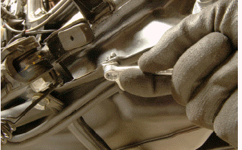
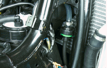
If required, correctly position the breather pipe by following the steps below: insert the transparent end of the breather pipe on the appropriate tank fitting and tighten the retaining clamp.
CAUTION
DURING INSTALLATION, MAKE SURE THAT THE PART OF PIPE CONNECTED TO THE TANK IS THE CLEAR ONE.
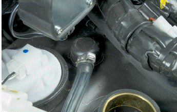
Lay the pipe along the right side of the vehicle making it adhere to the upper part of the fuel tank.
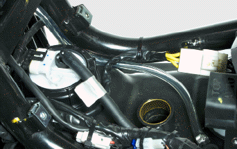
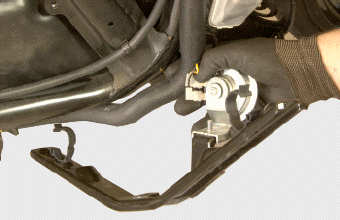
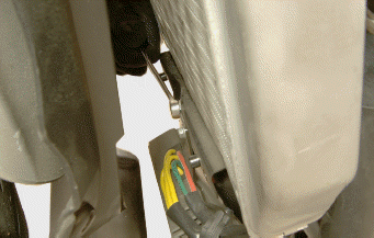
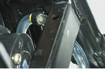
Hook the retaining clip on the rear hole of the inner bracket of the frame and lock the tube in correspondence with the yellow marking.
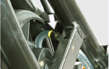
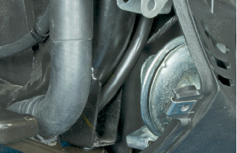
Bring the valve downwards and keep it from the inside to the crosspiece of the frame.
In this way it is ensured that the valve does not come into contact with the electric fan and the radiator.
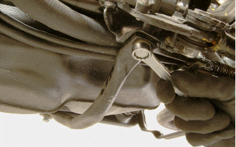
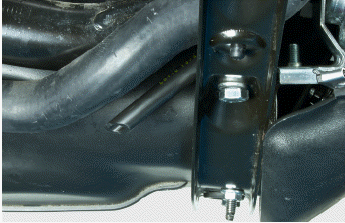
Drain the black rubber tube towards the seat of the horn and insert it in the support bracket of the crosspiece fixing the footrests.
Finally, let out, toward the rear side of the vehicle, the end part of the black rubber pipe.
CAUTION
MAKE SURE THAT ALONG THE PATH THERE ARE NO CHOKES IN THE BREATHER PIPE.
See also:
 PIAGGIO Beverly 300ie - Service manual > Front wheel housing
To remove the front wheel housing, proceed as follows: Remove the leg shield back plate; Remove the handlebar covers; Remove the fork; Release the indicated clamps from the wheel housing; Undo the three screws indicated and remove the wheel housing.
PIAGGIO Beverly 300ie - Service manual > Front mudguard
To remove the front mudguard, proceed as follows: On both sides of the vehicle, unscrew the indicated screws and remove the stanchion guard; Unscrew the three bolts indicated inside the mudguard; Detach the brake hose from the two indicated seats and remove the mudguard, pulling from the front.


