 Suzuki Burgman 400 - Service manual > General Description
Immobilizer Description (For E-02, 19, 24, 54)
The immobilizer, an anti-theft system, is installed as a standard equipment.
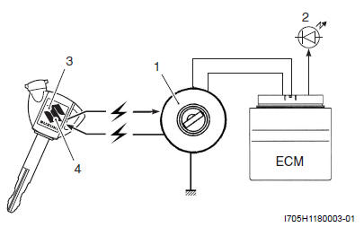
The immobilizer verifies that the key ID agrees with ECM ID by means of radio communication through the immobilizer antenna. When the ID agreement is verified, the system makes the engine ready to start.
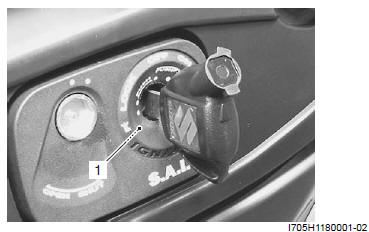
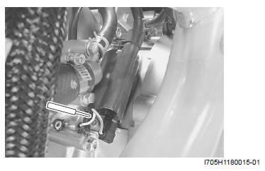
- Immobilizer antenna
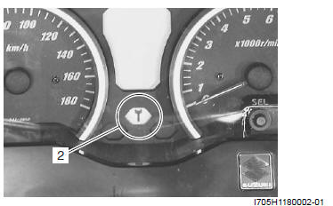
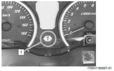
- Indicator light
- Immobilizer antenna
- Indicator light
- Transponder
- ID
Operation
When the ignition switch is turned ON with the engine stop switch in ON, the immobi-antenna and ECM are powered ON.
The ECM transmits a signal to the transponder through the immobi-antenna in order to make comparison between the key ID and ECM ID.
With the signal received, the transponder transmits the key ID signal to ECM so that ECM can make comparison with its own ID, and if it matches, the engine is made ready to start.
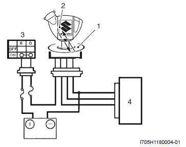
- Immobilizer antenna
- Transponder
- Ignition switch
- ECM
Also, when the ignition switch is turned ON, the indicator light flashes as many as the number of IDs registered in ECM. Thereafter, if the IDs are in agreement, the indicator light turns on for two seconds to notify of completion in successful communication.
If the indicator light (LED) flashes fast, it notifies of communication error or disagreement of ID.
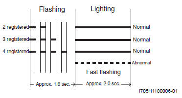
NOTE If the indicator light flashes fast, turn the ignition switch OFF then ON to make judgment again as there is possible misjudgment due to environmental radio interference.
! CAUTION When the battery performance is lowered in winter (low temperature), the system may at times makes a re-judgment at the time of beginning the starter motor operation. In this case, the indicator light operation starts immediately after the starter operation.
NOTE In the case that the LED flashes fast, remains lit or unlit, the probable cause of such a failure may be due to abnormal condition in the key, key cylinder, wiring harness or ECM.
(If such a failure exists, contact your distributor or dealer.)
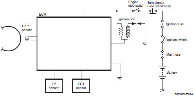
Schematic and Routing Diagram
Ignition System Diagram
Diagnostic Information and Procedures
Ignition System Symptom Diagnosis
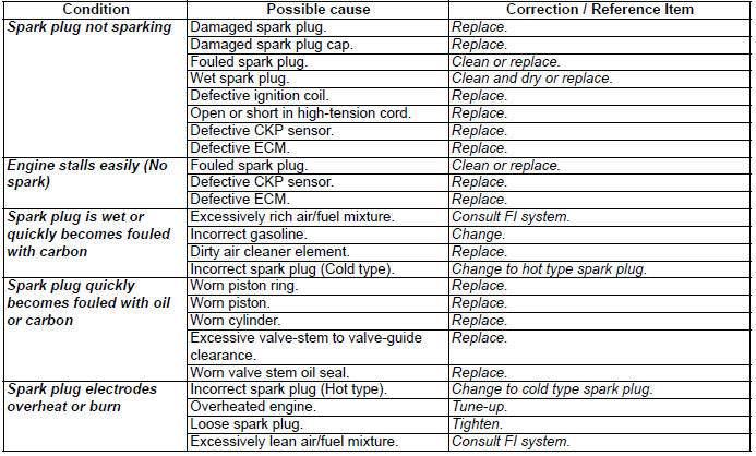
No Spark or Poor Spark
Troubleshooting
NOTE Make sure the engine stop switch is in the "RUN" position and side-stand is in up-right position.
Grasp the front or rear brake lever. Make sue the fuse is not blown and the battery is fully-charged before diagnosing.
Spark Plug Removal and Installation
Refer to "Spark Plug Removal and Installation".
Spark Plug Inspection and Cleaning
Refer to "Spark Plug Inspection and Cleaning".
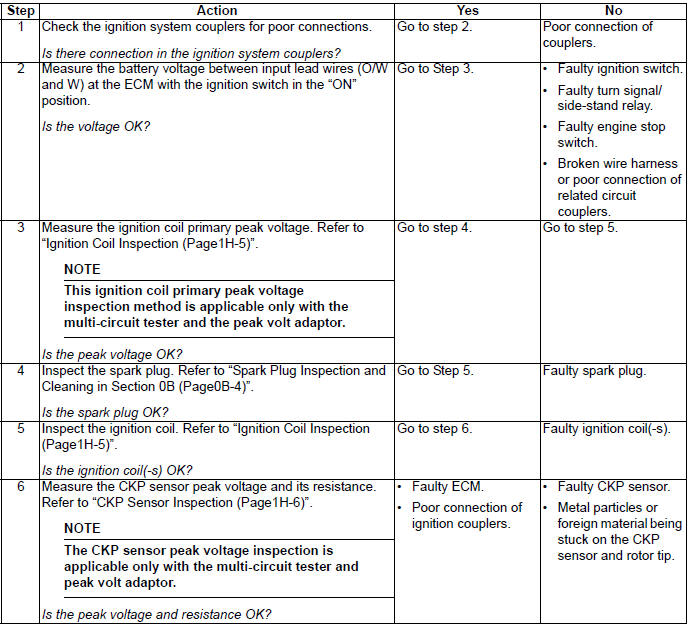
Ignition Coil Inspection
Refer to "Electrical Components Location ".
Ignition Coil Primary Peak Voltage
1) Remove the left footboard. Refer to "Footboard Removal and Installation ".
2) Disconnect the spark plug cap.
3) Connect new spark plug (1) to the spark plug cap and ground it on the cylinder.
NOTE Be sure that the spark plug is connected properly and the battery used is in fully-charged condition.
4) Connect the multi-circuit tester with the peak voltage adaptor as follows.
WARNING Do not touch the tester probes and spark plug to prevent an electric shock while testing.
NOTE Do not disconnect the ignition coil lead wires.
Special tool (A): 09900-25008 (Multi-circuit tester set)
Tester knob indication
Voltage ( )
)
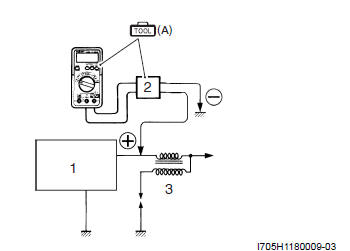
- ECM
- Peak voltage adapter
- Ignition coil
5) Press the starter button and allow the engine to crank for a few seconds, and then measure the ignition coil primary peak voltage.
6) Repeat above procedures a few times and measure the highest ignition coil primary peak voltage.
If the voltages are lower than standard values, inspect the ignition coil and the CKP sensor.
Ignition coil primary peak voltage
150 V and more
7) After measuring the ignition coil primary peak voltage, reinstall the removed parts.
See also:
 Suzuki Burgman 400 - Service manual > Ignition Coil Resistance
1) Remove the left footboard. Refer to "Footboard Removal and Installation ". 2) Disconnect the spark plug cap. 3) Disconnect the ignition coil lead wires. 4) Measure the ignition coil resistance in both the primary and secondary windings.


