 Suzuki Burgman 400 - Service manual > Ignition Coil Resistance
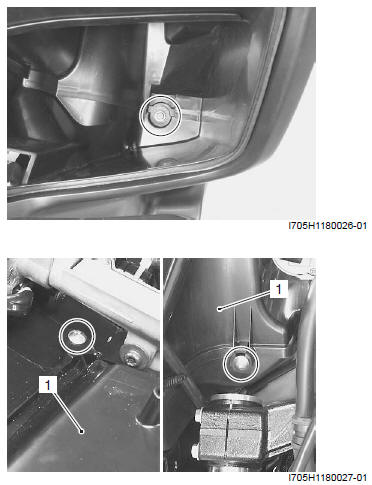
1) Remove the left footboard. Refer to "Footboard Removal and Installation ".
2) Disconnect the spark plug cap.
3) Disconnect the ignition coil lead wires.
4) Measure the ignition coil resistance in both the primary and secondary windings.
Special tool : 09900-25008 (Multi-circuit tester set)
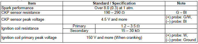
Ignition coil resistance
Primary: Approx. 1.2 - 3.5 Ω ( (+) terminal - (-) terminal)
Secondary: Approx. 15 - 30 kΩ ( (+) terminal - Spark plug cap)
Tester knob indication
Resistance (Ω)
5) After measure the ignition coil resistance, reinstall the removed parts.
Ignition Coil Assembly Removal and Installation
Refer to "Electrical Components Location".
Removal
1) Remove the front frame cover and left footboard.
Refer to "Footboard Removal and Installation".
2) Disconnect the spark plug cap.
3) Disconnect the lead wires and remove the ignition coil assembly.
Installation
Install the ignition coil assembly in the reverse order of removal.
Spark Plug Removal and Installation
Refer to "Spark Plug Inspection and Cleaning".
Spark Plug Inspection
Refer to "Spark Plug Inspection and Cleaning".
CKP Sensor Inspection
Refer to "Electrical Components Location ".
CKP Sensor Peak Voltage
1) Remove the meter panel. Refer to "Meter Panel Removal and Installation".
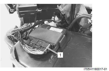
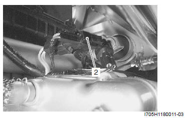
2) Disconnect the ECM coupler (1).
NOTE Make sure that all of the couplers are connected properly and the battery is fully-charged.
3) Connect the multi-circuit tester with the peak volt adaptor as follows.
Special tool (A): 09900-25008 (Multi-circuit tester set)
Tester knob indication: Voltage ( )
)
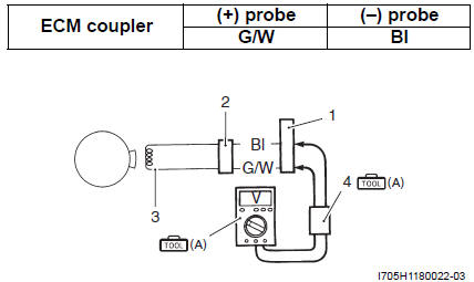
- ECM coupler
- CKP sensor coupler
- CKP sensor
- Peak voltage adaptor
4) Measure the CKP sensor peak voltage in the following procedures:
- Press the starter button and allow the engine to crank for a few seconds, and then measure the CKP sensor peak voltage.
5) Repeat the above procedures a few times and measure the highest CKP sensor peak voltage.
CKP sensor peak voltage
4.5 V and more (G/W - Bl)
6) If the peak voltage measured on the ECM coupler is lower than the standard value, measure the peak voltage on the CKP sensor coupler as follows.
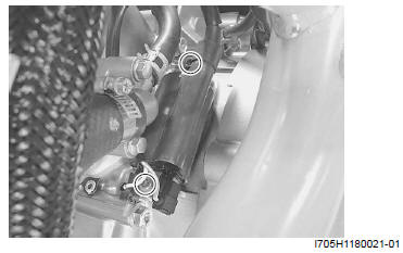
a) Disconnect the CKP sensor coupler (2).
b) Connect the multi-circuit tester with the peak voltage adaptor.
Special tool (A): 09900-25008 (Multi-circuit tester set)
Tester knob indication
Voltage ( )
)
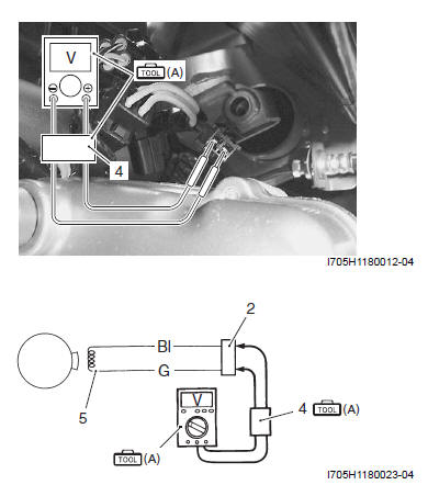
2. CKP sensor coupler
4. Peak volt adaptor
5. CKP sensor
c) Measure the CKP sensor peak voltage in the same manner as on the ECM coupler.
If the peak voltage on the CKP sensor lead wire couplers is within specification, but on the ECM coupler is out of specification, the wire harness must be replaced. If both peak voltages are out of specification, the CKP sensor must be replaced and rechecked.
CKP sensor peak voltage
4.5 V and more (G - Bl)
7) After measuring the CKP sensor peak voltage, reinstall the removed parts.
CKP Sensor Resistance
1) Disconnect the CKP sensor coupler (1).
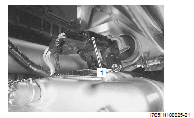
2) Measure the resistance between the lead wires and ground. If the resistance is not within the specified value, the CKP sensor must be replaced. Refer to "CKP Sensor Removal and Installation".
Resistance (Ω)
CKP sensor resistance
Approx. 190 - 290 Ω (G - Bl)
∞ Ω (G - Ground)
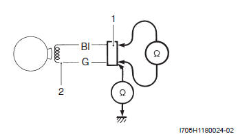
- CKP sensor coupler
- CKP sensor
3) After measuring the CKP sensor resistance, reinstall the removed parts.
CKP Sensor Removal and Installation
Refer to "CKP Sensor Removal and Installation".
Engine Stop Switch Inspection
Refer to "Engine Stop Switch Inspection".
Ignition Switch Inspection
Refer to "Ignition Switch Inspection".
Ignition Switch Removal and Installation
Removal
1) Disconnect the battery (-) cable.
2) Remove the front leg shield. Refer to "Front Leg Shield Cover Removal and Installation".
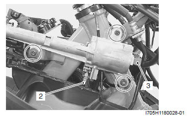
3) Remove the right front box inner cover (1).
4) Disconnect the immobilizer coupler. (Only for E-02, 19, 24, 54)
5) Disconnect the ignition switch coupler (2).
6) Remove the ignition switch.
7) Disconnect the seat-lock cable (3).
Installation
Installation is in the reverse order of removal.
Specifications
Service Data
Electrical
Unit: mm (in)
Special Tools and Equipment
Special Tool
 09900-25008
Multi-circuit tester set
09900-25008
Multi-circuit tester set
See also:
 Suzuki Burgman 400 - Service manual > General Description
Immobilizer Description (For E-02, 19, 24, 54) The immobilizer, an anti-theft system, is installed as a standard equipment. The immobilizer verifies that the key ID agrees with ECM ID by means of radio communication through the immobilizer antenna. When the ID agreement is verified, the system makes the engine ready to start. Immobilizer antenna Indicator light Immobilizer antenna Indicator light Transponder ID


