 Suzuki Burgman 400 - Service manual > General Description
Parking Brake System (Brake-lock System) Description
Parking Brake (Brake-lock) Operation
The brake-lock arm turns through the brake-lock cable as soon as pulling the brake-lock lever. The turning movement is converted to axial movement by the brake-lock adjuster connected to the body with the thread "A".
The axial movement transmits automatically from sleeve piston to adjust-bolt. The adjust-bolt presses brake pad to brake disk through the adjust-nut/caliper piston. In this bout, the adjust-bolt and adjust-nut move together with the relation as shown in the figure.
When releasing the brake-lock lever, each part return to home position, the caliper piston will be returned by an elasticity transform of piston seal, the adjust-bolt will be returned by the adjust-bolt spring, the brake-lock adjuster will be returned by the return-spring.
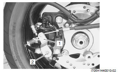
- Brake-lock arm
- Brake-lock adjuster
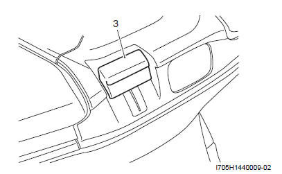
- Brake-lock lever
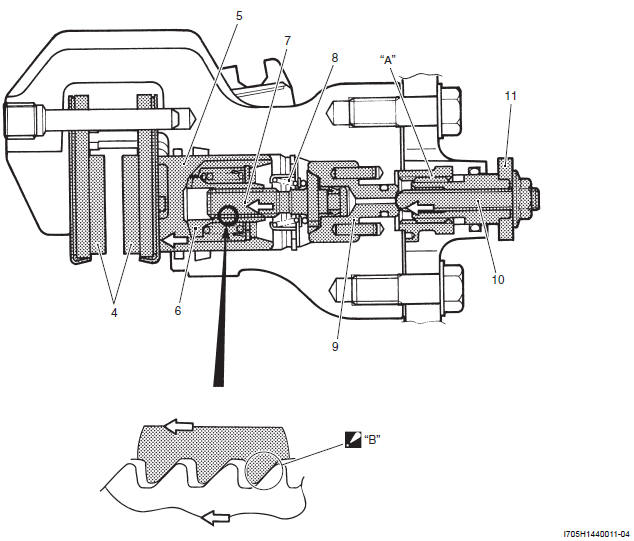
- Brake pad
- Caliper piston
- Adjust nut
- Adjust bolt
- Adjust bolt spring
- Sleeve piston
- Brake-lock adjuster
- Brake-lock arm
- Thread
- The adjust bolt presses the adjust nut.
Automatic Parking Brake Adjuster System (Automatic Brake-lock Adjuster System)
The automatic brake-lock adjuster system is equipped on the brake-lock. If the brake pad worn, the adjust-bolt/nut adjust the position of caliper piston so as to keep the certain clearance between brake pad and brake disk.
Operation (Normal Condition → Braking)
The hydraulic pressure by brake lever operation acts on the adjust-nut/caliper piston. The adjust-bolt threads and adjust-nut threads have a clearance. The piston stroke when braking is shorter than clearance, thus, the braking operation will finish without automatic brake-lock adjuster system operation.
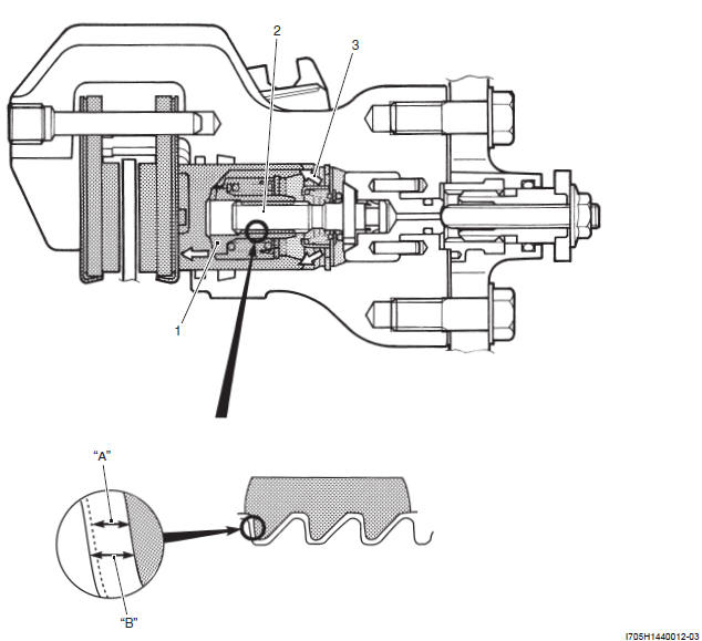
- Adjust nut
- Adjust bolt
- Hydraulic pressure
- Caliper piston stroke
- Clearance
Operation (Brake Pads are Worn → Braking → Automatic Adjuster Operate)
If braking when the brake pad being worn, the caliper piston/adjust nut move "A" until the clearance depended on abrasion is done away.
The axial movement "B" is converted to rotary movement and acts on the adjust bolt and adjust-nut. Only the adjust-bolt turns "C" because the caliper piston/adjust-nut is fixed to the brake pad with caliper piston groove and pad boss at "D". Thus, the adjust-bolt keeps original position with rotating as well as the caliper piston/adjust-nut moves outside.
The adjust-bolt stops rotating once the brake pad-to-disc clearance become zero, so the automatic adjuster operation is completed.
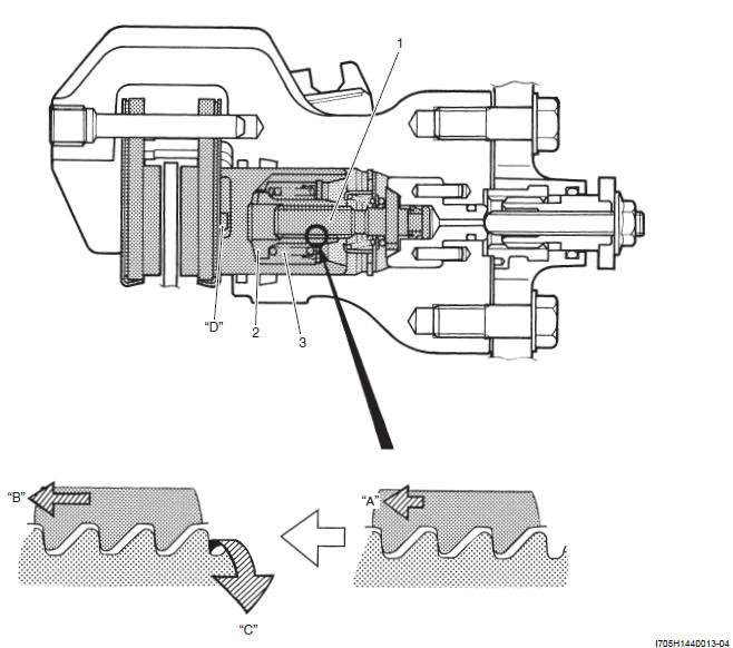
- Adjust bolt
- Adjust nut
- Adjust nut spring
Over-adjust Prevention Mechanism
When rapid braking "A", the automatic brake-lock adjuster operation works too fast "B".
The caliper piston/adjust nut is forced to stop "C" as soon as the brake pad contacts with brake disk, but the adjust bolt turns by inertia force "D" after that. The adjust bolt stops after the adjust-bolt/nut clearance becomes zero. On this account, the caliper piston/adjust nut can not return back "E" using the elasticity transform of piston seal when releasing the brake lever. It is the over-adjust condition.
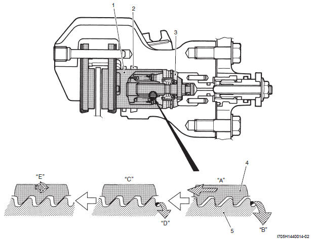
- Caliper piston
- Piston seal
- Hydraulic pressure
- Adjust nut
- Adjust bolt
- Rapid braking
- Rapid rotation
- Sudden stop
- Turn by inertia
- Impossible to return
The spring is equipped between the caliper piston and the adjust-nut for preventing the over-adjust, serves damper in term of rapid caliper piston movement.
The spring compress "A" as soon as the caliper piston moves exponentially "B", the adjust-nut moves "C", "D" behind time. Here with, it is possible to make correct clearance of the adjust bolt/nut because the inertia force with rapid movement does not work the adjust-bolt.
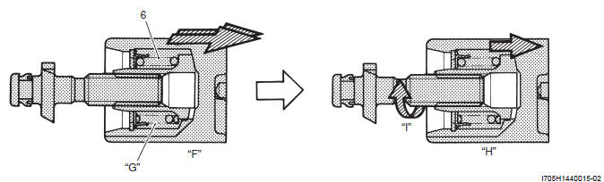
- Spring
"F": Rapid braking
"G": Spring compresses
"H": Spring tensions/adjuster nut moves
"I": Rotate
See also:
 Suzuki Burgman 400 - Service manual > Schematic and Routing Diagram
Parking Brake Cable (Brake-lock Cable) Routing Diagram Clamp Wire harness Pass the throttle cables through inside of the frame. Pass the throttle cables through under and inside of the frame.


