 Suzuki Burgman 400 - Service manual > Schematic and Routing Diagram
Parking Brake Cable (Brake-lock Cable) Routing Diagram
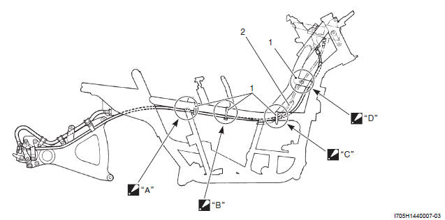
- Clamp
- Wire harness
- Pass the throttle cables through inside of the frame.
- Pass the throttle cables through under and inside of the frame.
Bind the brake-lock cable, starter motor lead wire and seat-lock cable together.
- Pass the throttle cables through inside of the frame.
Bind the brake-lock cable starter motor lead wire and seat-lock cable together.
- Pass the throttle cables through inside of the frame.
Repair Instructions
Parking Brake System (Brake-lock System) Inspection
Refer to "Parking Brake (Brake-lock) Inspection".
Parking Brake System (Brake-lock System) Removal and Installation
Refer to "Rear Brake Caliper Removal and Installation".
Parking Brake System (Brake-lock System) Disassembly and Assembly
Refer to "Rear Brake Caliper Disassembly and Assembly".
Parking Brake Cable (Brake-lock Cable) Removal and Installation
Refer to "Parking Brake Cable (Brake-lock Cable) Routing Diagram".
Removal
1) Remove the front box. Refer to "Front Box Removal and Installation".
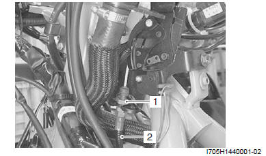
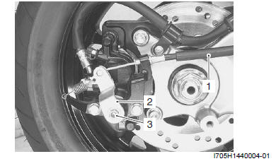
2) Loosen the brake-lock nut (1), remove the brake-lock cable (2).
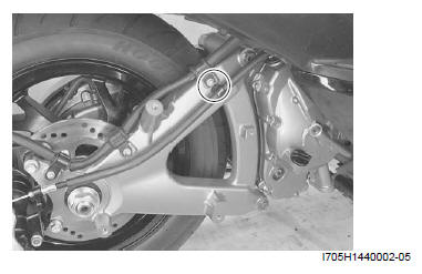
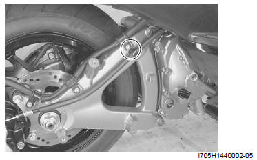
3) Remove the brake hose clamp.
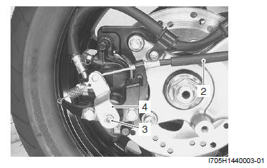
4) Remove the lock-nut (3) and remove the brake-lock arm (4).
5) Remove the brake-lock cable. Refer to "Parking Brake Cable (Brake-lock Cable) Routing Diagram".
Installation
1) Install the brake-lock cable. Refer to "Parking Brake Cable (Brake-lock Cable) Routing Diagram".
2) Assembly the brake-lock cable (1) to brake-lock arm (2), install the lock-nut (3). Refer to "Rear Brake Caliper Removal and Installation".
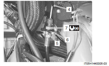
3) Pull the brake-lock lever (4) one notch.
4) Tighten the brake-lock cable adjust bolt (5) by hand until it contacts the holder (6).
5) Tighten the brake-lock cable lock-nut (7) to the specified torque.
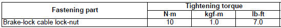
Tightening torque
Brake-lock cable lock-nut (a): 10 N*m (1.0 kgf-m, 7.0 lb-ft)
6) Install the brake hose clamp.
7) Install the front box. Refer to "Front Box Removal and Installation".
8) After installing, adjust the brake-lock. Refer to "Brake System Inspection".
Specifications
Tightening Torque Specifications
Reference: For the tightening torque of fastener not specified in this section, refer to "Tightening Torque Specifications".
See also:
 Suzuki Burgman 400 - Service manual > General Description
Parking Brake System (Brake-lock System) Description Parking Brake (Brake-lock) Operation The brake-lock arm turns through the brake-lock cable as soon as pulling the brake-lock lever. The turning movement is converted to axial movement by the brake-lock adjuster connected to the body with the thread "A".
Suzuki Burgman 400 - Service manual > Transmission / Transaxle
Precautions Precautions for Transmission/Transaxle Refer to "General Precautions". Automatic Transmission


