 Suzuki Burgman 400 - Service manual > Handlebars Inspection
Refer to "Handlebars Removal and Installation".
Inspect the handlebars for distortion and damage.
If any defect are found, replace the handlebars with a new one.
Steering Components
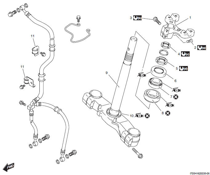
- Handlebar holder
- Handlebar holder set bolt
- Handlebar holder clamp bolt
- Steering stem lock nut
- Steering stem nut
- Dust seal
- Upper bearing
- Lower bearing
- Steering stem
- Lower inner race
- Front brake hose cramp
- : 23 N*m (2.3 kgf-m, 16.5 lb-ft)
- : 55 N*m (5.5 kgf-m, 40.0 lb-ft)
- : 30 N*m (3.0 kgf-m, 21.5 lb-ft)
- : 30 N*m (3.0 kgf-m, 21.5 lb-ft)
 : Apply grease.
 : Do not reuse.
Steering Removal and Installation
Removal
1) Support the motorcycle with a jack or wooden block.
2) Remove the front box. Refer to "Front Box Removal and Installation".
3) Remove the front forks. Refer to "Front Fork Removal and Installation". The front fork removal is not necessary unless the steering stem replacement or front fork disassembly work is required.
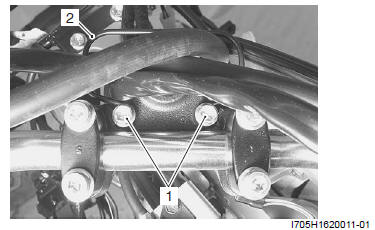
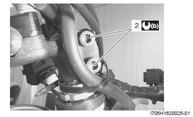
4) Remove the front brake hose clamp bolts (1) and remove the cable guide (2).
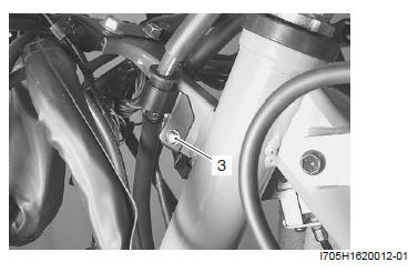
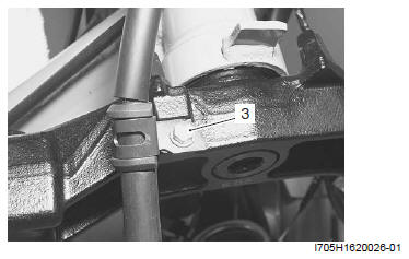
5) Remove the front brake hose clamp (3).
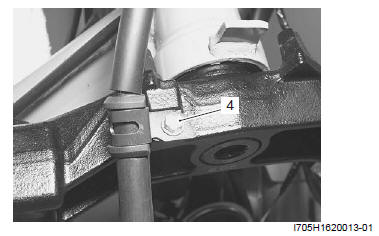
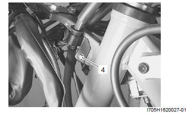
6) Remove the front brake hose clamp (4) from the steering stem.
! CAUTION
- Take care not to make air come in to the front brake system.
- Be careful not to drop the front brake caliper components.
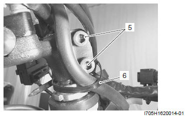
7) Loosen the handlebar holder clamp bolts (5) and remove the clamp (6).
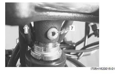
8) Remove the handlebar holder set bolt (7).
9) Remove the handlebar holder with handlebars.
! CAUTION This operation must be performed without causing undue stress to the brake hoses, lead wires and throttle cables.
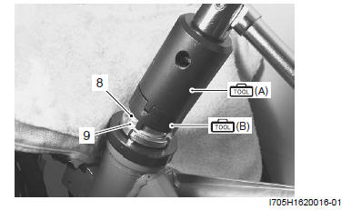
10) Remove the lock-nut (8) and washer (9) using the special tools.
Special tool
(A): 09940-14911 (Steering stem nut wrench)
(B): 09940-11420 (Steering stem nut socket)
11) Remove the steering stem nut (10) using the special tools and remove the steering stem.
NOTE Hold the steering stem by hand to prevent it from falling.
Special tool
(A): 09940-14911 (Steering stem nut wrench)
(C): 09940-11430 (Steering stem nut socket)
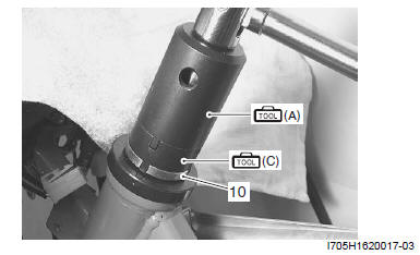
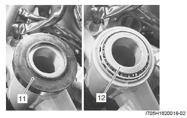
12) Remove the dust seal (11) and upper bearing (12).
Installation
Install the steering in the reverse order of removal.
Pay attention to the following points:
- Clean the steering related parts before installing.
Bearing
- Apply grease to the bearings, races and dust seals before remounting the steering stem.
: Grease
99000-25010 (SUZUKI SUPER GREASE A or equivalent)
Steering stem nut / Washer / Lock-nut
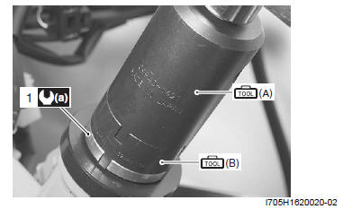
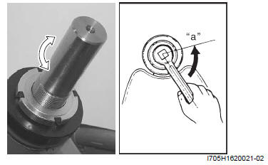
Tighten the steering stem nut (1) to the specified torque using the special tools.
Special tool
(A): 09940-14911 (Steering stem nut wrench)
(B): 09940-11430 (Steering stem nut socket)
Tightening torque
Steering stem nut (a): 30 N*m (3.0 kgf-m, 21.5 lb-ft)
- Turn the steering stem right and left 5 - 6 times to break-in the bearing.
- Loosen the steering stem nut 1/4 - 1/2 turn "a".
- In this condition, check that the steering stem can turn smoothly with
no rattle and stiffness.
If there is a rattle or heavy movement, adjust the tightness by the stem nut.
NOTE This adjustment will vary from motorcycle to motorcycle.
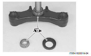
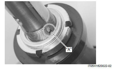
- Install the washer with its tab "A" engaged with the steering stem groove.
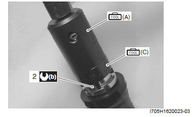
- Tighten the lock-nut (2) to the specified torque using the special tools.
NOTE Tightening the lock-nut can affect the steering stem nut adjustment. Therefore after tightening the lock-nut, check the steering movement again and adjust if necessary.
Special tool
(A): 09940-14911 (Steering stem nut wrench)
(C): 09940-11420 (Steering stem nut socket)
Tightening torque
Lock-nut (b): 30 N*m (3.0 kgf-m, 21.5 lb-ft)
Handlebar holder
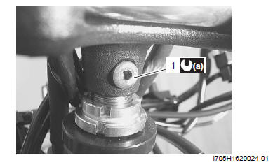
- Install the handlebar holder with the handlebars and tighten the handlebar holder set bolt (1) to the specified torque.
! CAUTION This operation must be performed without causing undue stress to the brake hoses, lead wires and throttle cables.
Tightening torque
Handlebar holder set bolt (a): 23 N*m (2.3 kgf-m, 16.5 lb-ft)
- Install the clamp and tighten the handlebar holder clamp bolts (2) to the specified torque.
Tightening torque
Handlebar holder clamp bolt (b): 55 N*m (5.5 kgf-m, 40.0 lb-ft)
- Install the front brake hose clamp (3) to the steering stem.
- Install the front brake hose clamp (4).
! CAUTION Take care not to make air come in to the front brake system.
- Perform the steering inspection after assembly has been completed.
See also:
 Suzuki Burgman 400 - Service manual > Steering / Handlebar
Repair Instructions Handlebars Components Throttle grip Rubber grip Handlebar switch box (RH) Handlebar switch box (LH) Rear view mirror Handle cover Handlebar holder Handlebar Handle expander Handle balancer expander Apply handle grip bond.
Suzuki Burgman 400 - Service manual > Steering Related Parts Inspection
Refer to "Steering Removal and Installation". Inspect the removed parts for the following abnormalities. Distortion of the steering stem Bearing wear or damage Abnormal bearing noise Race wear or damage


