 Suzuki Burgman 400 - Service manual > Steering Related Parts Inspection
Refer to "Steering Removal and Installation".
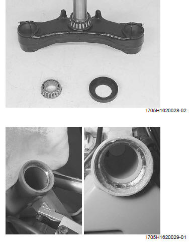
Inspect the removed parts for the following abnormalities.
- Distortion of the steering stem
- Bearing wear or damage
- Abnormal bearing noise
- Race wear or damage
If any abnormal points are found, replace defective parts with the new ones.
Steering System Inspection
Refer to "Steering System Inspection".
Steering Stem Bearing Removal and Installation
Refer to "Steering Components".
Removal
1) Remove the steering stem. Refer to "Steering Removal and Installation ".
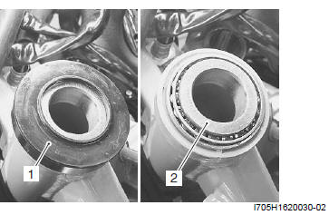
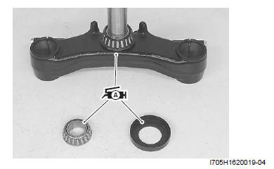
2) Remove the dust seal (1) and steering stem upper bearing (2).
3) Remove the steering stem lower bearing and inner race using a chisel.
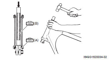
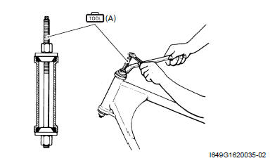
4) Remove the steering stem upper and lower bearing races using the special tools.
Special tool
(A): 09941-54911 (Bearing outer race remover)
(B): 09941-74911 (Steering bearing installer)
Installation
- Install the steering stem bearings in the reverse order of removal. Pay attention to the following points:
! CAUTION The removed bearings and races should be replaced with the new ones.
Outer race
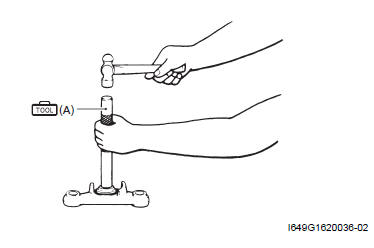
- Press in the upper and lower outer races using the special tool.
Special tool (A): 09941-34513 (Steering race installer)
Inner race
- Press in the lower inner race and bearing using the special tool.
Special tool (A): 09941-74911 (Steering bearing installer)
Bearing
- Apply grease to the bearings, races and dust seals before remounting the steering stem.
 : Grease 99000-25010
(SUZUKI SUPER GREASE A or equivalent)
: Grease 99000-25010
(SUZUKI SUPER GREASE A or equivalent)
- Instal the steering. Refer to "Steering Removal and Installation".
Steering Tension Adjustment
Check the steering movement in the following procedures:
1) By supporting the motorcycle with a jack, lift the front wheel unit is off the floor 20 - 30 mm (0.8 - 1.2 in).
2) Check to make sure that the cables and wire harnesses are properly routed.
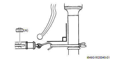
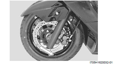
3) With the front wheel in the straight ahead state, hitch the spring scale (special tool) on one handlebar grip end as shown in the figure and read the graduation when the handlebar starts moving.
Initial force
200 - 500 g
Special tool (A): 09940-92720 (Spring scale)
4) Do the same on the other grip end.
5) If the initial force read on the scale when the handlebar starts turning is either to heavy or too light, adjust it till it satisfies the specification.
- First, loosen the front fork clamp bolts, lock-nut and steering stem nut, and then adjust the steering stem nut by loosening or tightening it.
- Tighten the steering stem nut, lock-nut and front fork clamp bolts to the specified torque and recheck the initial force with the spring scale according to the previously described procedures.
- If the initial force is found within the specified range, adjustment has been completed.
NOTE Hold the front fork legs, move them back and forth and make sure that the steering is not loose.
Specifications
Tightening Torque Specifications
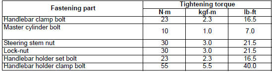
NOTE The specified tightening torque is also described in the following.
Reference: For the tightening torque of fastener not specified in this section, refer to "Tightening Torque Specifications".
Special Tools and Equipment
Recommended Service Material
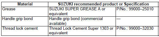
NOTE Required service material is also described in the following.
Special Tool
 09940-11420
Steering stem nut socket
09940-11420
Steering stem nut socket
 09940-11430
Steering stem nut socket
09940-11430
Steering stem nut socket
 09940-14911
Steering stem nut wrench
09940-14911
Steering stem nut wrench
 09940-92720
Spring scale
09940-92720
Spring scale
 09941-34513
Steering race installer
09941-34513
Steering race installer
 09941-54911
Bearing outer race remover
09941-54911
Bearing outer race remover
 09941-74911
Steering bearing installer
09941-74911
Steering bearing installer
See also:
 Suzuki Burgman 400 - Service manual > Handlebars Inspection
Refer to "Handlebars Removal and Installation". Inspect the handlebars for distortion and damage. If any defect are found, replace the handlebars with a new one.


